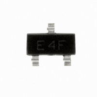
HSMP-3814-TR1G Avago Technologies US Inc., HSMP-3814-TR1G Datasheet - Page 3

HSMP-3814-TR1G
Manufacturer Part Number
HSMP-3814-TR1G
Description
DIODE PIN ATTENUATOR 100V SOT-23
Manufacturer
Avago Technologies US Inc.
Datasheet
1.HSMP-3812-BLKG.pdf
(9 pages)
Specifications of HSMP-3814-TR1G
Package / Case
SOT-23-3, TO-236-3, Micro3™, SSD3, SST3
Diode Type
PIN - 1 Pair Common Cathode
Voltage - Peak Reverse (max)
100V
Current - Max
1A
Capacitance @ Vr, F
0.35pF @ 50V, 1MHz
Resistance @ If, F
3 Ohm @ 100mA, 100MHz
Configuration
Dual Common Cathode
Reverse Voltage
100 V
Forward Continuous Current
1 A
Termination Style
SMD/SMT
Carrier Life
1.5 us
Maximum Diode Capacitance
0.35 pF @ 50 V
Maximum Operating Temperature
+ 150 C
Maximum Series Resistance @ Maximum If
3 Ohm @ 100 mA
Maximum Series Resistance @ Minimum If
53 Ohm (Typ) @ 1 mA
Minimum Operating Temperature
- 65 C
Mounting Style
SMD/SMT
Recovery Time
300 nS
Diode Case Style
SOT-23
Breakdown Voltage
100V
Capacitance Ct
0.27pF
Leaded Process Compatible
Yes
Peak Reflow Compatible (260 C)
Yes
Rohs Compliant
Yes
Lead Free Status / RoHS Status
Lead free / RoHS Compliant
Power Dissipation (max)
-
Lead Free Status / Rohs Status
Lead free / RoHS Compliant
Other names
516-1800-2
HSMP-3814-TR1G
HSMP-3814-TR1G
Available stocks
Company
Part Number
Manufacturer
Quantity
Price
Company:
Part Number:
HSMP-3814-TR1G
Manufacturer:
AGILENT
Quantity:
510
Part Number:
HSMP-3814-TR1G
Manufacturer:
AVAGO/安华高
Quantity:
20 000
Typical Parameters at T
Notes:
3. Typical values were derived using limited samples during initial product characterization and may not be representative of the overall distribution.
3
Typical Parameters at T
Part Number
HSMP-
381x
Test Conditions
Figure 1. RF Capacitance vs. Reverse
Bias.
Figure 4. Forward Current vs. Forward
Voltage.
0.45
0.40
0.35
0.30
0.25
0.20
0.15
0.01
100
0.1
10
1
0
0
2
V
F
0.2
4
REVERSE VOLTAGE (V)
– FORWARD VOLTAGE (mA)
125 C 25 C –50 C
1 MHz
30 MHz
frequency>100 MHz
6
0.4
8
10 12
0.6
C
C
= 25°C
= 25°C (unless otherwise noted), Single Diode
0.8
Series Resistance
14
f = 100 MHz
I
16
F
1.0
= 1 mA
R
S
53
18 20
(Ω)
1.2
Typical Applications for Multiple Diode Products
INPUT
Figure 5. Four Diode π Attenuator. See Application Note 1048
for Details.
10000
1000
Figure 2. RF Resistance vs. Forward
Bias Current, f = 100MHz
100
10
1
0.01
I
F
Carrier Lifetime
– FORWARD BIAS CURRENT (mA)
I
R
I
F
= 250 mA
= 50 mA
W (ns)
1500
0.1
1
T
T
T
A
A
A
= +85 C
= +25 C
= –55 C
VARIABLE BIAS
10
VOLTAGE
FIXED
BIAS
Reverse Recovery Time
100
90% Recovery
I
F
V
= 20 mA
R
T
rr
300
= 10 V
(ns)
Figure 3. 2nd Harmonic Input
Intercept Point vs. Diode RF
Resistance.
120
100
110
90
80
70
60
50
40
1000
Diode Mounted as a
Series Attenuator
in a 50 Ohm Microstrip
and Tested at 123 MHz
DIODE RF RESISTANCE (OHMS)
100
Capacitance
0.27 @ 50 V
RF IN/OUT
f = 1 MHz
C
Total
T
(pF)
10


