MMDL301T1G ON Semiconductor, MMDL301T1G Datasheet

DIODE SCHOTTKY 200MW 30V SOD-323

MMDL301T1G

Manufacturer Part Number
MMDL301T1G
Description
DIODE SCHOTTKY 200MW 30V SOD-323
Manufacturer
ON Semiconductor
Datasheet

Specifications of MMDL301T1G

Diode Type
Schottky - Single
Voltage - Peak Reverse (max)
30V
Capacitance @ Vr, F
1.5pF @ 15V, 1MHz
Power Dissipation (max)
200mW
Package / Case
SC-76, SOD-323, UMD2
Rectifier Type
Schottky Diode
Configuration
Single
Peak Rep Rev Volt
30V
Rev Curr
0.2uA
Forward Voltage
0.6V
Operating Temp Range
-55C to 150C
Package Type
SOD-323
Operating Temperature Classification
Military
Mounting
Surface Mount
Pin Count
2
Lead Free Status / RoHS Status
Lead free / RoHS Compliant
Current - Max
-
Resistance @ If, F
-
Lead Free Status / Rohs Status
Compliant
Other names
MMDL301T1GOSTR

Available stocks

Company
Part Number
Manufacturer
Quantity
Price
Part Number:
MMDL301T1G
Manufacturer:
ON Semiconductor
Quantity:
32 249
Part Number:
MMDL301T1G
Manufacturer:
ON Semiconductor
Quantity:
5
Part Number:
MMDL301T1G
Manufacturer:
ON/安森美
Quantity:
20 000
Company:
Part Number:
MMDL301T1G
Quantity:
4 500
Company:
Part Number:
MMDL301T1G
Quantity:
4 500
MMDL301T1G
Silicon Hot-Carrier Diodes
Schottky Barrier Diode
VHF detector applications. They are readily adaptable to many other
fast switching RF and digital applications. They are supplied in an
inexpensive plastic package for low−cost, high−volume consumer
and industrial/commercial requirements. They are available in a
Surface Mount package.
Features
Stresses exceeding Maximum Ratings may damage the device. Maximum
Ratings are stress ratings only. Functional operation above the Recommended
Operating Conditions is not implied. Extended exposure to stresses above the
Recommended Operating Conditions may affect device reliability.
1. FR−5 Minimum Pad
MAXIMUM RATINGS
THERMAL CHARACTERISTICS
© Semiconductor Components Industries, LLC, 2010
September, 2010− Rev. 2
ELECTRICAL CHARACTERISTICS
Reverse Voltage
Total Device Dissipation FR−5 Board,
(Note 1) @T
Derate above 25°C
Thermal Resistance, Junction−to−Ambient
Junction and Storage Temperature Range
Reverse Breakdown Voltage
Total Capacitance
Reverse Leakage
Forward Voltage
Forward Voltage
These devices are designed primarily for high−efficiency UHF and
Compliant
Extremely Low Minority Carrier Lifetime − 15 ps (Typ)
Very Low Capacitance − 1.5 pF (Max) @ V
Low Reverse Leakage − I
These Devices are Pb−Free, Halogen Free/BFR Free and are RoHS
(I
(V
(V
(I
(I
R
F
F
R
R
= 1.0 mAdc) Figure 4
= 10 mAdc) Figure 4
= 10 mA)
= 15 V, f = 1.0 MHz) Figure 1
= 25 V) Figure 3
Characteristic
A
Characteristic
= 25°C
Rating
(T
J
= 125°C unless otherwise noted)
R
= 13 nAdc (Typ)
Symbol
V
(BR)R
C
V
V
I
(T
R
T
F
F
A
Symbol
Symbol
T
= 25°C unless otherwise noted)
R
J
V
P
, T
qJA
R
D
Min
stg
30
R
= 15 V
−55 to +150
0.38
0.52
Typ
0.9
13
Value
Max
1.57
200
635
30
Max
0.45
200
1.5
0.6
1
mW/°C
°C/W
Unit
Unit
nAdc
mW
Unit
Vdc
Vdc
°C
pF
V
V
†For information on tape and reel specifications,
MMDL301T1G
including part orientation and tape sizes, please
refer to our Tape and Reel Packaging Specifications
Brochure, BRD8011/D.
*Date Code orientation may vary depending
Device
HOT−CARRIER DETECTOR
upon manufacturing location.
AND SWITCHING DIODES
(Note: Microdot may be in either location)
1
ORDERING INFORMATION
30 VOLTS SILICON
4T
M
G
CATHODE
MARKING DIAGRAM
http://onsemi.com
1
SOD−323
(Pb−Free)
Package
= Device Code
= Date Code*
= Pb−Free Package
2
Publication Order Number:
4T M G
G
ANODE
CASE 477
SOD−323
PLASTIC
STYLE 1
3000 / Tape & Reel
2
Shipping
MMDL301T1/D

Related parts for MMDL301T1G

MMDL301T1G Summary of contents

Page 1

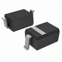
... Code orientation may vary depending upon manufacturing location. ORDERING INFORMATION Device Package Shipping MMDL301T1G SOD−323 3000 / Tape & Reel (Pb−Free) †For information on tape and reel specifications, including part orientation and tape sizes, please refer to our Tape and Reel Packaging Specifications Brochure, BRD8011/D ...

Page 2

TYPICAL ELECTRICAL CHARACTERISTICS 2.8 2.4 2.0 1.6 1.2 0.8 0 3.0 6.0 9 REVERSE VOLTAGE (VOLTS) R Figure 1. Total Capacitance 100°C A 1.0 75°C 0.1 25°C 0.01 0.001 0 ...

Page 3

... NOTE 5 NOTE 3 *For additional information on our Pb−Free strategy and soldering details, please download the ON Semiconductor Soldering and Mounting Techniques Reference Manual, SOLDERRM/D. ON Semiconductor and are registered trademarks of Semiconductor Components Industries, LLC (SCILLC). SCILLC reserves the right to make changes without further notice to any products herein ...

Related keywords