AD676BD Analog Devices Inc, AD676BD Datasheet - Page 7
AD676BD
Manufacturer Part Number
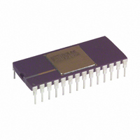
AD676BD
Description
ADC Single SAR 100KSPS 16-Bit Parallel 28-Pin SBCDIP
Manufacturer
Analog Devices Inc
Datasheet
1.AD676JNZ.pdf
(16 pages)
Specifications of AD676BD
Package
28SBCDIP
Resolution
16 Bit
Sampling Rate
100 KSPS
Architecture
SAR
Number Of Analog Inputs
1
Digital Interface Type
Parallel
Input Type
Voltage
Polarity Of Input Voltage
Bipolar
Rohs Status
RoHS non-compliant
Number Of Bits
16
Sampling Rate (per Second)
100k
Data Interface
Parallel
Number Of Converters
2
Power Dissipation (max)
480mW
Voltage Supply Source
Analog and Digital, Dual ±
Operating Temperature
-40°C ~ 85°C
Mounting Type
Through Hole
Package / Case
28-CDIP (0.600", 15.24mm)
For Use With
AD676-EB - BOARD EVAL SAMPLING ADC AD676
Lead Free Status / RoHS Status
Available stocks
Company
Part Number
Manufacturer
Quantity
Price

Part Number:
AD676BD
Manufacturer:
ADI/亚德诺
Quantity:
20 000


NYQUIST FREQUENCY
An implication of the Nyquist sampling theorem, the “Nyquist
frequency” of a converter is that input frequency which is one
half the sampling frequency of the converter.
TOTAL HARMONIC DISTORTION
Total harmonic distortion (THD) is the ratio of the rms sum of
the harmonic components to the rms value of a full-scale input
signal and is expressed in percent (%) or decibels (dB). For in-
put signals or harmonics that are above the Nyquist frequency,
the aliased components are used.
SIGNAL-TO-NOISE PLUS DISTORTION RATIO
Signal-to-noise plus distortion is defined to be the ratio of the
rms value of the measured input signal to the rms sum of all
other spectral components below the Nyquist frequency, includ-
ing harmonics but excluding dc.
GAIN ERROR
The last transition should occur at an analog value 1.5 LSB be-
low the nominal full scale (4.99977 volts for a 5 V range). The
gain error is the deviation of the actual difference between the
first and last code transition from the ideal difference between
the first and last code transition.
BIPOLAR ZERO ERROR
Bipolar zero error is the difference between the ideal midscale
input voltage (0 V) and the actual voltage producing the
midscale output code.
DIFFERENTIAL NONLINEARITY (DNL)
In an ideal ADC, code transitions are one LSB apart. Differen-
tial nonlinearity is the maximum deviation from this ideal value.
It is often specified in terms of resolution for which no missing
codes are guaranteed.
INTEGRAL NONLINEARITY (INL)
The ideal transfer function for an ADC is a straight line bisect-
ing the center of each code drawn between “zero” and “full
scale.” The point used as “zero” occurs 1/2 LSB before the
most negative code transition. “Full scale” is defined as a level
1.5 LSB beyond the most positive code transition. Integral
nonlinearity is the worst-case deviation of a code center average
from the straight line.
REV. A
–7–
BANDWIDTH
The full-power bandwidth is that input frequency at which the
amplitude of the reconstructed fundamental is reduced by 3 dB
for a full-scale input.
INTERMODULATION DISTORTION (IMD)
With inputs consisting of sine waves at two frequencies, fa and
fb, any device with nonlinearities will create distortion products,
of order (m+n), at sum and difference frequencies of mfa
where m, n = 0, 1, 2, 3. . . . Intermodulation terms are those for
which m or n is not equal to zero. For example, the second or-
der terms are (fa + fb) and (fa – fb), and the third order terms
are (2 fa + fb), (2 fa – fb), (fa + 2 fb) and (fa – 2 fb). The IMD
products are expressed as the decibel ratio of the rms sum of the
measured input signals to the rms sum of the distortion terms.
The two signals applied to the converter are of equal amplitude,
and the peak value of their sum is –0.5 dB from full scale. The
IMD products are normalized to a 0 dB input signal.
APERTURE DELAY
Aperture delay is the time required after SAMPLE pin is taken
LOW for the internal sample-hold of the AD676 to open, thus
holding the value of V
APERTURE JITTER
Aperture jitter is the variation in the aperture delay from sample
to sample.
POWER SUPPLY REJECTION
DC variations in the power supply voltage will affect the overall
transfer function of the ADC, resulting in zero error and gain er-
ror changes. Power supply rejection is the maximum change in
either the bipolar zero error or gain error value. Additionally,
there is another power supply variation to consider. AC ripple
on the power supplies can couple noise into the ADC, resulting
in degradation of dynamic performance. This is displayed in
Figure 16.
INPUT SETTLING TIME
Settling time is a function of the SHA’s ability to track fast
slewing signals. This is specified as the maximum time required
in track mode after a full-scale step input to guarantee rated
conversion accuracy.
Definition of Specifications–
lN
.
AD676
nfb,
Related parts for AD676BD
Image
Part Number
Description
Manufacturer
Datasheet
Request
R

Part Number:
Description:
BOARD EVAL SAMPLING ADC AD676
Manufacturer:
Analog Devices Inc
Datasheet:

Part Number:
Description:
±1.7g Dual-Axis IMEMS Accelerometer Evaluation Board
Manufacturer:
Analog Devices Inc
Datasheet:
Part Number:
Description:
Inertial Sensor Evaluation System
Manufacturer:
Analog Devices Inc
Datasheet:
Part Number:
Description:
Manufacturer:
Analog Devices Inc
Datasheet:
Part Number:
Description:
Manufacturer:
Analog Devices Inc
Datasheet:
Part Number:
Description:
Manufacturer:
Analog Devices Inc
Datasheet:
Part Number:
Description:
Manufacturer:
Analog Devices Inc
Datasheet:
Part Number:
Description:
Manufacturer:
Analog Devices Inc
Datasheet:
Part Number:
Description:
Manufacturer:
Analog Devices Inc
Datasheet:
Part Number:
Description:
Manufacturer:
Analog Devices Inc
Datasheet:
Part Number:
Description:
Manufacturer:
Analog Devices Inc
Datasheet:
Part Number:
Description:
Manufacturer:
Analog Devices Inc
Datasheet:
Part Number:
Description:
Manufacturer:
Analog Devices Inc
Datasheet: