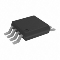
AD7418ARM Analog Devices Inc, AD7418ARM Datasheet - Page 10

AD7418ARM
Manufacturer Part Number
AD7418ARM
Description
ADC Single SAR 10-Bit Serial 8-Pin MSOP
Manufacturer
Analog Devices Inc
Datasheet
1.AD7418ARZ.pdf
(24 pages)
Specifications of AD7418ARM
Package
8MSOP
Resolution
10 Bit
Architecture
SAR
Number Of Analog Inputs
1
Digital Interface Type
Serial (2-Wire, I2C)
Input Type
Voltage
Polarity Of Input Voltage
Unipolar
Rohs Status
RoHS non-compliant
Function
Temp Monitoring System (Sensor)
Topology
ADC, Comparator, Register Bank
Sensor Type
Internal
Sensing Temperature
-40°C ~ 125°C
Output Type
I²C™
Output Alarm
No
Output Fan
Yes
Voltage - Supply
2.7 V ~ 5.5 V
Operating Temperature
-40°C ~ 125°C
Mounting Type
Surface Mount
Package / Case
8-TSSOP, 8-MSOP (0.118", 3.00mm Width)
For Use With
EVAL-AD7416/7/8EBZ - BOARD EVALUATION FOR AD7416/7/8
Lead Free Status / RoHS Status
Available stocks
Company
Part Number
Manufacturer
Quantity
Price
Part Number:
AD7418ARM
Manufacturer:
ADI/亚德诺
Quantity:
20 000
Company:
Part Number:
AD7418ARM-REEL7
Manufacturer:
AD
Quantity:
5 510
Company:
Part Number:
AD7418ARM-REEL7
Manufacturer:
AD
Quantity:
5 510
Company:
Part Number:
AD7418ARMZ
Manufacturer:
ST
Quantity:
6 219
Part Number:
AD7418ARMZ
Manufacturer:
ADI/亚德诺
Quantity:
20 000
Part Number:
AD7418ARMZ-REEL
Manufacturer:
ADI/亚德诺
Quantity:
20 000
Company:
Part Number:
AD7418ARMZ-REEL7
Manufacturer:
MAXIM
Quantity:
1 480
Part Number:
AD7418ARMZ-REEL7
Manufacturer:
ADI/亚德诺
Quantity:
20 000
AD7416/AD7417/AD7418
TERMINOLOGY
Relative Accuracy
Relative accuracy or endpoint nonlinearity is the maximum
deviation from a straight line passing through the endpoints of
the ADC transfer function.
Differential Nonlinearity
This is the difference between the measured and the ideal 1 LSB
change between any two adjacent codes in the ADC.
Offset Error
This is the deviation of the first code transition (0000…000) to
(0000…001) from the ideal, that is, GND + 1 LSB.
Offset Error Match
This is the difference in offset error between any two channels.
Gain Error
This is the deviation of the last code transition (1111…110) to
(1111…111) from the ideal, that is, VREF − 1 LSB, after the
offset error has been adjusted out.
Rev. I | Page 10 of 24
Gain Error Match
This is the difference in gain error between any two channels.
Track-and-Hold Acquisition Time
Track-and-hold acquisition time is the time required for the
output of the track-and-hold amplifier to reach its final value,
within ±½ LSB, after the end of conversion (the point at which
the track-and-hold returns to track mode). It also applies to
situations where a change in the selected input channel takes
place or where there is a step input change on the input voltage
applied to the selected A
means that the user must wait for the duration of the track-and-
hold acquisition time after the end of conversion, or after a
channel change or step input change to A
another conversion, to ensure that the part operates to
specification.
IN
input of the AD7417 or AD7418. It
IN
before starting


