70TPS12PBF Vishay, 70TPS12PBF Datasheet - Page 3
70TPS12PBF
Manufacturer Part Number
70TPS12PBF
Description
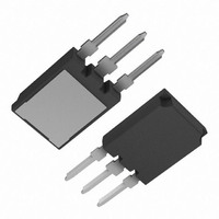
SCR PH CONTR 1200V 70A SUPER-247
Manufacturer
Vishay
Specifications of 70TPS12PBF
Scr Type
Standard Recovery
Voltage - Off State
1200V
Voltage - Gate Trigger (vgt) (max)
1.5V
Voltage - On State (vtm) (max)
1.4V
Current - On State (it (av)) (max)
70A
Current - On State (it (rms)) (max)
75A
Current - Gate Trigger (igt) (max)
100mA
Current - Hold (ih) (max)
200mA
Current - Off State (max)
15mA
Current - Non Rep. Surge 50, 60hz (itsm)
1400A @ 50Hz
Operating Temperature
-40°C ~ 125°C
Mounting Type
Through Hole
Package / Case
Super-247
Current - On State (it (rms) (max)
75A
Breakover Current Ibo Max
1400 A
Rated Repetitive Off-state Voltage Vdrm
1200 V
Off-state Leakage Current @ Vdrm Idrm
1 mA
Forward Voltage Drop
1.4 V
Gate Trigger Voltage (vgt)
1.5 V
Maximum Gate Peak Inverse Voltage
10 V
Gate Trigger Current (igt)
100 mA
Holding Current (ih Max)
200 mA
Mounting Style
SMD/SMT
Peak Repetitive Off-state Voltage, Vdrm
1.2kV
Gate Trigger Current Max, Igt
100mA
Current It Av
70A
On State Rms Current It(rms)
75A
Peak Non Rep Surge Current Itsm 50hz
1.4kA
Lead Free Status / RoHS Status
Lead free / RoHS Compliant
Other names
VS-70TPS12PBF
VS-70TPS12PBF
VS70TPS12PBF
VS70TPS12PBF
VS-70TPS12PBF
VS70TPS12PBF
VS70TPS12PBF
Available stocks
Company
Part Number
Manufacturer
Quantity
Price
Company:

Part Number:
70TPS12PBF
Manufacturer:
MOLEX
Quantity:
12 000
Company:
Part Number:
70TPS12PBF
Manufacturer:
VIR
Quantity:
200
Part Number:
70TPS12PBF
Manufacturer:
VISHAY/威世
Quantity:
20 000


Document Number: 94391
Triggering
Thermal-Mechanical Specifications
ΔR Conduction (per Junction)
(The following table shows the increment of thermal resistance R
P
P
I
- V
V
I
V
I
T
T
R
R
R
wt
T
GM
GT
GD
GM
G(AV)
GT
GD
J
stg
Device
70TPS
thJC
thJA
thCS
GM
Parameters
Max. peak Gate Power
Max. average Gate Power
Max. peak Gate Current
Max. peak negative Gate Voltage
Max. required DC Gate Voltage
to trigger
Max. required DC Gate Current
to trigger
Max. DC Gate Voltage not to trigger
Max. DC Gate Current not to trigger
Max. Junction Temperature Range
Max. Storage Temperature Range
Max. Thermal Resistance Junction
to Case
Max. Thermal Resistance Junction
to Ambient
Max. Thermal Resistance Case
to Heatsink
Approximate Weight
Mounting Torque
Case Style
Marking Device
Parameters
0.078
180
o
0.092
120
Sine half wave conduction
o
0.117
90
Max.
Min.
o
0.172
60
- 40 to 125
- 40 to 150
o
70TPS..
70TPS..
6 (0.21)
12 (10)
6 (5)
0.25
0.27
270
100
4.0
2.5
2.5
1.5
1.1
0.2
10
10
80
40
6
Super-247
70TPS16
0.302
30
thJC
o
when devices operate at different conduction angles than DC)
Kg-cm
(lbf-in)
g (oz.)
Units
Units
°C/W
mA
mA
W
°C
A
V
V
0.053
180
o
t = 30µs
T
T
T
T
T
T
T
DC operation
Mounting surface, smooth and greased
J
J
J
J
J
J
J
= - 40°C
= 25°C
= 125°C
= - 40°C
= 25°C
= 125°C, V
= 125°C
0.092
120
70TPS..PbF SAFE
Rect. wave conduction
o
0.125
DRM
90
Conditions
Conditions
o
= rated value
Anode supply = 6V
resistive load
Bulletin I2184 rev A 01/07
0.180
60
o
0.306
30
www.vishay.com
IR
o
Series
°C/W
Units
3
Related parts for 70TPS12PBF
Image
Part Number
Description
Manufacturer
Datasheet
Request
R

Part Number:
Description:
SCR PH CONTR 1200V 70A SUPER-247
Manufacturer:
Vishay
Datasheet:

Part Number:
Description:
357-036-542-201 CARDEDGE 36POS DL .156 BLK LOPRO
Manufacturer:
Vishay
Datasheet:
Part Number:
Description:
357-036-542-201 CARDEDGE 36POS DL .156 BLK LOPRO
Manufacturer:
Vishay
Datasheet:
Part Number:
Description:
357-036-542-201 CARDEDGE 36POS DL .156 BLK LOPRO
Manufacturer:
Vishay
Datasheet:
Part Number:
Description:
357-036-542-201 CARDEDGE 36POS DL .156 BLK LOPRO
Manufacturer:
Vishay
Datasheet:
Part Number:
Description:
357-036-542-201 CARDEDGE 36POS DL .156 BLK LOPRO
Manufacturer:
Vishay
Datasheet:
Part Number:
Description:
357-036-542-201 CARDEDGE 36POS DL .156 BLK LOPRO
Manufacturer:
Vishay
Datasheet:
Part Number:
Description:
357-036-542-201 CARDEDGE 36POS DL .156 BLK LOPRO
Manufacturer:
Vishay
Datasheet:
Part Number:
Description:
357-036-542-201 CARDEDGE 36POS DL .156 BLK LOPRO
Manufacturer:
Vishay
Datasheet:
Part Number:
Description:
357-036-542-201 CARDEDGE 36POS DL .156 BLK LOPRO
Manufacturer:
Vishay
Datasheet:
Part Number:
Description:
357-036-542-201 CARDEDGE 36POS DL .156 BLK LOPRO
Manufacturer:
Vishay
Datasheet:
Part Number:
Description:
357-036-542-201 CARDEDGE 36POS DL .156 BLK LOPRO
Manufacturer:
Vishay
Datasheet:
Part Number:
Description:
357-036-542-201 CARDEDGE 36POS DL .156 BLK LOPRO
Manufacturer:
Vishay
Datasheet:
Part Number:
Description:
357-036-542-201 CARDEDGE 36POS DL .156 BLK LOPRO
Manufacturer:
Vishay
Datasheet:
Part Number:
Description:
357-036-542-201 CARDEDGE 36POS DL .156 BLK LOPRO
Manufacturer:
Vishay
Datasheet: