TYN1012RG STMicroelectronics, TYN1012RG Datasheet - Page 5
TYN1012RG
Manufacturer Part Number
TYN1012RG
Description
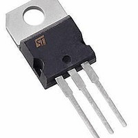
SCR 12A 1000V 30MA TO-220-3
Manufacturer
STMicroelectronics
Datasheet
1.TYN812RG.pdf
(12 pages)
Specifications of TYN1012RG
Scr Type
Standard Recovery
Voltage - Off State
1000V
Voltage - Gate Trigger (vgt) (max)
1.3V
Voltage - On State (vtm) (max)
1.6V
Current - On State (it (av)) (max)
8A
Current - On State (it (rms)) (max)
12A
Current - Gate Trigger (igt) (max)
15mA
Current - Hold (ih) (max)
30mA
Current - Off State (max)
5µA
Current - Non Rep. Surge 50, 60hz (itsm)
140A, 145A
Operating Temperature
-40°C ~ 125°C
Mounting Type
Through Hole
Package / Case
TO-220AB
Current - On State (it (rms) (max)
12A
Breakover Current Ibo Max
145 A
Rated Repetitive Off-state Voltage Vdrm
600 V
Off-state Leakage Current @ Vdrm Idrm
5 uA
Forward Voltage Drop
1.6 V
Gate Trigger Voltage (vgt)
1.3 V
Maximum Gate Peak Inverse Voltage
5 V
Gate Trigger Current (igt)
15 mA
Holding Current (ih Max)
30 mA
Mounting Style
Through Hole
Lead Free Status / RoHS Status
Lead free / RoHS Compliant
Other names
497-6782-5
TYN1012RG
TYN1012RG
Available stocks
Company
Part Number
Manufacturer
Quantity
Price
Company:

Part Number:
TYN1012RG
Manufacturer:
ST-CHN
Quantity:
6 500
Part Number:
TYN1012RG
Manufacturer:
ST
Quantity:
20 000


TN12, TS12 and TYNx12 Series
Figure 9.
Figure 11. Surge peak on-state current versus
Figure 13. On-state characteristics (maximum
200
100
10.0
150
140
130
120
110
100
10
1.0
90
80
70
60
50
40
30
20
10
0.1
0
1
0.0
0
1
I
I
dV/dt[R
TM
TSM
(A)
V =0.85V
R =30m
T =105°C
Repetitive
T max.:
t0
d
(A)
0.5
C
j
TS12
T
j
=max
GK
200
Relative variation of dV/dt immunity
versus gate-cathode resistance
(typical values) for TS12 series
number of cycles
values)
1.0
] / dV/dt[
TN12 / TYN12
1.5
400
10
T =25°C
R
j
Non repetitive
T initial=25°C
Number of cycles
GK
j
2.0
=220 ]
R
V
GK
TM
600
2.5
(k )
(V)
3.0
800
100
3.5
4.0
1000
t =10ms
V = 0.67 x V
p
D
One cycle
T
j
= 125°C
4.5
DRM
1000
1200
5.0
Figure 10. Relative variation of dV/dt immunity
Figure 12. Non-repetitive surge peak on-state
Figure 14. Thermal resistance junction to
4.0
3.5
3.0
2.5
2.0
1.5
1.0
0.5
0.0
100
2000
1000
80
60
40
20
100
0
10
0
dV/dt[C
0.01
R
0
V = 0.67 x V
th(j-a)
I
D
TSM
R
T
GK
j
= 125°C
= 220
2
(A), I t (A s)
(°C/W)
GK
25
DRM
dI/dt limitation
versus gate-cathode capacitance
(typical values) for TS12 series
current for a sinusoidal pulse with
width tp < 10 ms, and
corresponding values of I²t
ambient versus copper surface
under tab (epoxy printed circuit
board FR4, copper thickness:
35 µm) (DPAK and D
] / dV/dt[
2
4
D PAK
2
2
6
50
0.10
R
GK
DPAK
8
=220 ]
C
t (ms)
S(cm²)
p
GK
75
I
TSM
10
(nF)
TS12
12
I t
2
100
1.00
TN12 / TYN12
2
14
Characteristics
PAK)
TN12 / TYN12
16
125
T initial = 25°C
TS12
j
18
10.00
150
20
5/12
Related parts for TYN1012RG
Image
Part Number
Description
Manufacturer
Datasheet
Request
R

Part Number:
Description:
STMicroelectronics [RIPPLE-CARRY BINARY COUNTER/DIVIDERS]
Manufacturer:
STMicroelectronics
Datasheet:
Part Number:
Description:
STMicroelectronics [LIQUID-CRYSTAL DISPLAY DRIVERS]
Manufacturer:
STMicroelectronics
Datasheet:

Part Number:
Description:
BOARD EVAL FOR MEMS SENSORS
Manufacturer:
STMicroelectronics
Datasheet:
Part Number:
Description:
NPN TRANSISTOR POWER MODULE
Manufacturer:
STMicroelectronics
Datasheet:
Part Number:
Description:
TURBOSWITCH ULTRA-FAST HIGH VOLTAGE DIODE
Manufacturer:
STMicroelectronics
Datasheet:
Part Number:
Description:
Manufacturer:
STMicroelectronics
Datasheet:
Part Number:
Description:
DIODE / SCR MODULE
Manufacturer:
STMicroelectronics
Datasheet:
Part Number:
Description:
DIODE / SCR MODULE
Manufacturer:
STMicroelectronics
Datasheet:
Part Number:
Description:
Search -----> STE16N100
Manufacturer:
STMicroelectronics
Datasheet:
Part Number:
Description:
Search ---> STE53NA50
Manufacturer:
STMicroelectronics
Datasheet:
Part Number:
Description:
NPN Transistor Power Module
Manufacturer:
STMicroelectronics
Datasheet:
Part Number:
Description:
DIODE / SCR MODULE
Manufacturer:
STMicroelectronics
Datasheet: