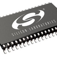
SI3210M-KTR Silicon Laboratories Inc, SI3210M-KTR Datasheet - Page 32

SI3210M-KTR
Manufacturer Part Number
SI3210M-KTR
Description
RF Wireless Misc Sgl Ch SLIC/Codec w/ MOSFET Decoder
Manufacturer
Silicon Laboratories Inc
Type
ProSLIC Programmable CMOS SLICr
Datasheet
1.SI3210MPPQX-EVB.pdf
(146 pages)
Specifications of SI3210M-KTR
Operating Frequency
200 MHz
Supply Current
4 mA
Operating Temperature Range
- 40 C to + 100 C
Package / Case
TSSOP-14
Mounting Style
SMD/SMT
Lead Free Status / RoHS Status
Lead free / RoHS Compliant
- Current page: 32 of 146
- Download datasheet (860Kb)
Si3210/Si3211
2.1.5. Power Monitoring and Line Fault Detection
In addition to reporting voltages and currents, the ProSLIC continuously monitors the power dissipated in each
external bipolar transistor. Real-time output power of any one of the six linefeed transistors can be read by setting
the Power Monitor Pointer (direct Register 76) to point to the desired transistor and then reading the Line Power
Output Monitor (direct Register 77).
The real-time power measurements are low-pass filtered and compared to a maximum power threshold. Maximum
power thresholds and filter time constants are software-programmable and should be set for each transistor pair
based on the characteristics of the transistors used. Table 25 describes the registers associated with this function.
If the power in any external transistor exceeds the programmed threshold, a power alarm event is triggered. The
ProSLIC sets the Power Alarm register bit, generates an interrupt (if enabled), and automatically enters the Open
state (if AOPN = 1). This feature protects the external transistors from fault conditions and, combined with the loop
voltage and current monitors, allows diagnosis of the type of fault condition present on the line.
The value of each thermal low-pass filter pole is set according to the equation:
where is the thermal time constant of the transistor package, 4096 is the full range of the 12-bit register, and 800
is the sample rate in hertz. Generally = 3 seconds for SOT223 packages and = 0.16 seconds for SOT23, but
check with the manufacturer for the package thermal constant of a specific device. For example, the power alarm
threshold and low-pass filter values for Q5 and Q6 using a SOT223 package transistor are computed as follows:
Thus, indirect Register 34 should be set to 150Dh.
32
*Note: The ProSLIC uses registers that are both directly and indirectly mapped.
Loop Voltage Sense (V
Battery Voltage Sense 1 (V
Battery Voltage Sense 2 (V
Transistor 1 Current Sense
Transistor 2 Current Sense
Transistor 3 Current Sense
Transistor 4 Current Sense
Transistor 5 Current Sense
Transistor 6 Current Sense
A “direct” register is one that is mapped directly.
RING Voltage Sense
Loop Current Sense
TIP Voltage Sense
Parameter
Table 24. Measured Real-Time Linefeed Interface Characteristics
TIP
– V
BAT
BAT
RING
)
)
)
Thermal LPF register
–78.75 to +78.5 mA
–94.5 to +94.5 V
Measurement
0 to 81.35 mA
0 to 81.35 mA
0 to 80.58 mA
0 to 80.58 mA
0 to –95.88 V
0 to –95.88 V
0 to –95.88 V
0 to –95.88 V
0 to 9.59 mA
0 to 9.59 mA
Range
Rev. 1.5
=
Resolution
------------------
800
0.319 mA
0.319 mA
0.316 mA
0.316 mA
4096
1.25 mA
0.376 V
0.376 V
0.376 V
0.376 V
37.6 µA
37.6 µA
1.5 V
2
3
VBATS1[7:0]
VBATS2[7:0]
VRING[7:0]
VTIP[7:0]
Register
LCS[5:0]
LVS[6:0]
IQ1[7:0]
IQ2[7:0]
IQ3[7:0]
IQ4[7:0]
IQ5[7:0]
IQ6[7:0]
LCSP,
LVSP,
Bits
Direct Register 78
Direct Register 79
Direct Register 81
Direct Register 82
Direct Register 83
Direct Register 80
Direct Register 84
Direct Register 85
Direct Register 86
Direct Register 87
Direct Register 88
Direct Register 89
Location*
Related parts for SI3210M-KTR
Image
Part Number
Description
Manufacturer
Datasheet
Request
R

Part Number:
Description:
IC SLIC/CODEC PROG 1CH 38QFN
Manufacturer:
Silicon Laboratories Inc
Datasheet:
Part Number:
Description:
IC SLIC/CODEC PROG 1CH 38TSSOP
Manufacturer:
Silicon Laboratories Inc
Datasheet:

Part Number:
Description:
IC SLIC/CODEC PROG 1CH 38QFN
Manufacturer:
Silicon Laboratories Inc
Datasheet:
Part Number:
Description:
IC SLIC/CODEC PROG 1CH 38TSSOP
Manufacturer:
Silicon Laboratories Inc
Datasheet:
Part Number:
Description:
IC SLIC/CODEC PROG 1CH 38TSSOP
Manufacturer:
Silicon Laboratories Inc
Datasheet:
Part Number:
Description:
IC SLIC/CODEC PROG 38TSSOP
Manufacturer:
Silicon Laboratories Inc
Datasheet:
Part Number:
Description:
Manufacturer:
Silicon Laboratories Inc
Datasheet:
Part Number:
Description:
Manufacturer:
Silicon Laboratories Inc
Datasheet:
Part Number:
Description:
Manufacturer:
Silicon Laboratories Inc
Datasheet:

Part Number:
Description:
RF Wireless Misc Sgl Ch SLIC/Codec w/ MOSFET Decoder
Manufacturer:
Silicon Laboratories Inc
Datasheet:
Part Number:
Description:
C�/SI3210 QFN EVALUATION BOARD WITH DISCRETE LINE INTERFACE
Manufacturer:
Silicon Laboratories Inc
Datasheet:
Part Number:
Description:
QFN 38/I�/SINGLE-CHANNEL SLIC/CODEC WITH DTMF DECODER AND BJT/INDUCTOR DC-D
Manufacturer:
Silicon Laboratories Inc
Part Number:
Description:
IC SLIC/CODEC PROGRAMMBL 38TSSOP
Manufacturer:
Silicon Laboratories Inc
Datasheet:
Part Number:
Description:
IC SLIC/CODEC PROG 38TSSOP
Manufacturer:
Silicon Laboratories Inc
Datasheet:

Part Number:
Description:
IC SLIC/CODEC PROG 38QFN
Manufacturer:
Silicon Laboratories Inc
Datasheet:


