9-1393792-0 TE Connectivity, 9-1393792-0 Datasheet - Page 97
9-1393792-0
Manufacturer Part Number
9-1393792-0
Description
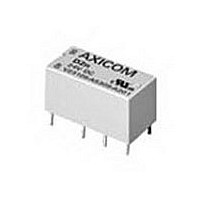
Electromechanical Relay DPDT 3A 24VDC 3.872KOhm Through Hole
Manufacturer
TE Connectivity
Type
Signal Relayr
Specifications of 9-1393792-0
Contact Arrangement
DPDT
Dc Coil Voltage
24 V
Coil Current
6.2 mA
Mounting
Through Hole
Relay Construction
Non-Latching
Coil Voltage Dc
24V
Contact Form
2 Form C
Voltage Rating (vdc)
220V
Voltage Rating (vac)
250V
Dropout Volt (min)
1.2VDCV
Coil Resistance
3.872kohm
Pick-up Voltage (max)
19.2VDC
Maximum Power Rating
60W/125VA
Operate Time
5ms
Contact Current Rating
3A
Contact Material
AgNi/Au
Coil Suppression Diode
No
Push To Test Button
No
Led Indicator
No
Seal
Unsealed
Product Height (mm)
11mm
Product Depth (mm)
10mm
Product Length (mm)
20.2mm
Operating Temp Range
-25C to 85C
Pin Count
8
Mounting Style
Through Hole
Termination Style
PC Pin
Package / Case
DIP
Lead Free Status / Rohs Status
Compliant


Dimensions are shown for
reference purposes only.
Features
Contact Data @ 23 C
Arrangement: 2 Form C (DPDT) bifurcated contacts.
Material: Gold overlay on silver nickel.
Rating:
UL/CSA Rating: 1A @ 30VDC; 300mA @ 110VDC;
Expected Mechanical Life: Approx. 100 million ops.
Expected Electrical Life:
Initial Contact Resistance: 50 milliohms @ 10mA, 20mV.
Thermoelectric potential: <10 V.
High Frequency Data
Capacitance: Between Open Contacts: 2pF, max.
RF Characteristics: Isolation at 100 / 900 MHz: -39.0 db / -20.7 db.
Initial Dielectric Strength
Between Open Contacts: 1,000Vrms for 1 minute. (1,500Vrms on
Between Coil and Contacts: 1,500Vrms for 1 minute. (single coil relay).
Between Poles: 1,000Vrms for 1 minute.
Surge Voltage Resistance per Bellcore TR-NWT-001089 (2 / 10 s):
Surge Voltage Resistance per FCC 68 (10 / 160 s):
Initial Insulation Resistance
Between Mutually Insulated Conductors: 10
• Surface and through hole mounting types.
• Breakdown voltage between contacts and coil: 1,500Vrms.
• Surge withstand between contacts and coil: 2,500V (Bellcore).
• High capacity contact: 2A @ 30VDC.
• 2 Form C contact arrangement.
• Board space saving, vertical mount (14.6 x 7.2mm surface area).
• Immersion cleanable, plastic sealed case.
• Single and dual coil latching versions available.
• Basic insulation (coil-to-contact) according to EN 60950 / UL 1950.
• Ultrasonic cleaning is not recommended.
Between Open Contacts: 2,000V.
Between Coil and Contacts: 2,500V (single coil relay).
Between Poles: 2,500V.
Between Open Contacts: 1,500V.
Between Coil and Contacts: 1,500V (single coil relay).
Between Poles: 1,500V.
Max. Switching Voltage: 250VAC, 220VDC.
Max. Switching Current: 5A.
Max Carrying Current: 2A.
Max Switching Power: 60W, DC; 62.5VA, AC.
Min. Permissible Load: 100 V.
Between Coil and Contacts: 1.5pF, max.
Between Poles: 1pF, max.
500mA @ 120VAC; 250mA @ 240VAC.
Insertion loss at 100 / 900 MHz: -0.02 db / -0.27 db.
V. S. W. R. at 100 / 900 MHz: 1.04 db / 1.40 db.
request, consult factory for availability).
50 million ops. @ 10mA, 12V,
10 million ops. @ 100mA, 6V.
1 million ops. @ 1A, 30V,
500,000 ops. @ 500mA, 60V.
200,000 ops. @ 2A, 30V.
Dimensions are in inches over
(millimeters) unless otherwise
specified.
9
ohms @ 500VDC.
Catalog 1308242
Issued 3-03
V23079 (P2)
5 Amp Switching, High Dielectric
DPDT Polarized
FCC Part 68
PC Board Relay
Users should thoroughly review the technical data before selecting a product part
number. It is recommended that users also seek out the pertinent approvals files of
the agencies/laboratories and review them to ensure the product meets the
requirements for a given application.
Coil Data @ 23 C
Operate Data @ 23 C
Operate Time (at nominal voltage): 3 ms, typ.; 5 ms, max.
Reset Time (at nominal voltage): 3 ms, typ.; 5 ms, max.
Release Time (non-latching w/o diode in parallel): 2 ms, typ.; 4 ms, max.
Release Time (non-latching with diode in parallel): 4 ms, typ.; 6 ms, max.
Bounce Time (at contact close): 1 ms, typ.; 3 ms, max.
Maximum Switching Rate (no load): 50 operations/s.
Environmental Data
Temperature Range: -40 C to +85 C.
Maximum Allowable Coil Temperature: 110 C.
Thermal Resistance: < 165K/W.
Shock, half sinus, 11 ms: Functional: 50g.
Shock, half sinus, 11 ms: Destructive: 150g.
Vibration, 10-1,000 Hz.: Functional: 35g.
Needle Flame Test: Application time 20s, burning time <15s.
Resistance to Soldering Heat: 260 C for 10s.
Mechanical Data
Termination: Through hole or surface mount printed circuit terminals.
Mounting Position: Any.
Enclosure: Immersion cleanable (IP67) plastic case.
Weight: .084 oz. (2.5g) approximately.
Voltage: 3-24V.
Nominal Power: 70mW-140mW, dependent on model. See chart below.
Must Operate Voltage: 75% of nominal or less.
Must Release Voltage: 10% of nominal or more.
Non-Latching, 140mW Nominal Power
Single Coil Latching, 70mW Nominal Power
Dual Coil Latching, 140mW Nominal Power
Nominal
Voltage
(VDC)
12
24
12
24
12
24
File E48393
File LR45064
3
4.5
5
6
9
3
4.5
5
6
9
3
4.5
5
6
9
Specifications and availability
subject to change.
Must Operate
Operating Range @ 23 C
Voltage
(VDC)
18.0
18.0
18.0
2.25
3.375
3.75
4.50
6.75
9.0
2.25
3.375
3.75
4.5
6.75
9.0
2.25
3.375
3.75
4.5
6.75
9.0
series
Voltage
(VDC)
Max.
10.9
13.0
19.6
26.1
52.3
13.8
15.3
18.5
27.7
37.0
74.0
10.9
13.0
19.6
26.1
52.3
9.8
6.5
9.2
6.5
9.8
Voltage
@ 85 C
(VDC)
Max.
10.3
13.8
27.7
14.6
19.6
39.2
3.4
5.1
5.7
6.8
4.8
7.3
8.1
9.8
–
–
–
–
–
–
–
www.tycoelectronics.com
Technical support:
Refer to inside back cover.
1,029
4,114
1,157
2,057
8,228
1,029
4,114
Resistance
145
178
257
578
128
289
357
514
145
178
257
578
64.3
64.3
@ 23 C
AXICOM
Coil
15
18
26
58
13
29
36
51
15
18
26
58
103
411
116
206
823
103
411
6
6
325
Related parts for 9-1393792-0
Image
Part Number
Description
Manufacturer
Datasheet
Request
R

Part Number:
Description:
CRIMP, RECEPTACLE
Manufacturer:
TE Connectivity
Datasheet:

Part Number:
Description:
PIGGYBACK DISCONNECT, 6.35MM, CRIMP BLUE
Manufacturer:
TE Connectivity
Datasheet:

Part Number:
Description:
Manufacturer:
TE Connectivity
Datasheet:

Part Number:
Description:
CRIMP TERMINAL, FEMALE, BLUE
Manufacturer:
TE Connectivity
Datasheet:
Part Number:
Description:
Manufacturer:
TE Connectivity
Datasheet:

Part Number:
Description:
CONN HEADR BRKWAY .100 13POS R/A
Manufacturer:
Tyco Electronics
Datasheet:
Part Number:
Description:
CONN HEADR BRKWAY .100 13POS R/A
Manufacturer:
Tyco Electronics
Datasheet:
Part Number:
Description:
CONN HDR BRKWAY .100 13POS VERT
Manufacturer:
Tyco Electronics
Datasheet:
Part Number:
Description:
CONN HDR BRKWAY .100 13POS VERT
Manufacturer:
Tyco Electronics
Datasheet:
Part Number:
Description:
CONN HDR BRKWAY .100 13POS VERT
Manufacturer:
Tyco Electronics
Datasheet:
Part Number:
Description:
CONN HEADR BRKWAY .100 13POS R/A
Manufacturer:
Tyco Electronics
Datasheet:
Part Number:
Description:
CONN HEADR BRKWAY .100 13POS STR
Manufacturer:
Tyco Electronics
Datasheet:
Part Number:
Description:
CONN HEADR BRKWAY .100 13POS STR
Manufacturer:
Tyco Electronics
Datasheet:
Part Number:
Description:
CONN HEADR BRKWAY .100 13POS STR
Manufacturer:
Tyco Electronics
Datasheet:
Part Number:
Description:
CONN HEADR BRKWAY .100 13POS R/A
Manufacturer:
Tyco Electronics
Datasheet: