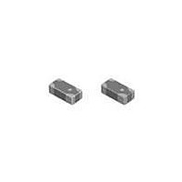
LDC311G6003B-601 Murata, LDC311G6003B-601 Datasheet

LDC311G6003B-601
Manufacturer Part Number
LDC311G6003B-601
Description
Filters LDC311G6003B-601
Manufacturer
Murata
Type
Chip Multilayer Devicesr
Series
LDCr
Datasheet
1.LDC311G6003B-601.pdf
(2 pages)
Specifications of LDC311G6003B-601
Product
Directional Couplers
Frequency
1700 MHz
Impedance
50 Ohms
Package / Case
1206 (3216 metric)
Operating Temperature Range
- 40 C to + 85 C
Termination Style
Radial
Frequency Range
1441 MHz +/- 12 MHz
Lead Free Status / RoHS Status
Lead free / RoHS Compliant
8
!Note
• This PDF catalog is downloaded from the website of Murata Manufacturing co., ltd. Therefore, it’s specifications are subject to change or our products in it may be discontinued without advance notice. Please check with our
• This PDF catalog has only typical specifications because there is no space for detailed specifications. Therefore, please approve our product specifications or transact the approval sheet for product specifications before ordering.
sales representatives or product engineers before ordering.
LDC15450M25Q-360
LDC15707M21Q-360
LDC15836M30Q-392
LDC15874M27Q-359
LDC15897M26SB008
LDC15906M19SB001
LDC151G4418Q-352
LDC151G7313Q-360
LDC151G7424Q-392
LDC151G7421Q-359
LDC151G8117Q-352
LDC151G8620Q-359
LDC151G8824Q-393
Part Number
LDC15 Series
LDC21 Series
Microwave Components
0.25
0.2 0.1
Frequency
12.5MHz
17.5MHz
19.0MHz
22.5MHz
37.5MHz
37.5MHz
100MHz
115MHz
1732.5
1747.5
+0.15
Range
–0.10
(MHz)
50MHz
51MHz
12MHz
30MHz
836.5
897.5
906.0
All the technical data and information contained herein are
subject to change without prior notice.
1441
1747
1810
1865
1880
9MHz
450
707
874
0.3 0.1
(3)
(4)
(2)
(3)
1.00 0.05
Directional Input Mark
0.50 0.15
2.0 0.1
(2)
(5)
0.65 0.05
0.35 0.1
Chip Multilayer Hybrid Couplers
Coupling
(6)
(1)
(1)
(4)
1.8dB
1.0dB
1.0dB
1.0dB
1.0dB
1.0dB
1.0dB
1.0dB
1.0dB
1.0dB
1.2dB
1.0dB
1.0dB
25.1
21.1
30.6
27.2
26.4
19.3
18.9
13.6
24.1
21.2
17.0
20.5
24.7
(dB)
0.3
+0.1
-0.2
(1)
(2)(5) :
(3)
(4)
(6)
0.15 max.
0.23 max.
0.20 max.
0.20 max.
0.15 max.
0.22 max.
0.23 max.
0.42 max.
0.20 max.
0.22 max.
0.25 max.
0.22 max.
0.20 max.
Insertion
(at 25 C)
(at 25 C)
(at 25 C)
(at 25 C)
(at 25 C)
(at 25 C)
(at 25 C)
(at 25 C)
(at 25 C)
(at 25 C)
(at 25 C)
(at 25 C)
(at 25 C)
:
:
:
(1)
(2)
(3)
(4)
:
Loss
Terminate
IN
GND
Main Out
Coupled Out
(dB)
: Output
: Input
: Coupling
: Terminate
0.40 max.
0.95 0.1
Directional Coupler
(in mm)
(in mm)
Isolation
(min.)
38.0
35.0
38.0
42.0
32.0
24.0
30.0
35.0
32.0
34.0
32.0
(dB)
-
-
LDC18_Q Series
VSWR
(max.)
1.5
1.4
1.4
1.4
1.4
1.4
1.4
1.4
1.4
1.4
1.4
1.4
1.4
Characteristic
(Nom.) (ohm)
Impedance
0.35 0.15
50
50
50
50
50
50
50
50
50
50
-
-
-
(2)
(3)
(50ohm Load)
(50ohm Load)
(50ohm Load)
(50ohm Load)
(50ohm Load)
(50ohm Load)
(50ohm Load)
(50ohm Load)
(50ohm Load)
(50ohm Load)
(50ohm Load)
(50ohm Load)
(50ohm Load)
Continued on the following page.
1.6 0.1
A
0.9 0.1
Capacity
Power
3 max.
3 max.
3 max.
3 max.
3 max.
3 max.
3 max.
3 max.
3 max.
3 max.
3 max.
3 max.
3 max.
(W)
(1)
(4)
(1): Main OUT
(2): IN
(3): Coupled OUT
(4): Terminate
A: Directional Input Mark
UMTS(Band5/8)
UMTS(Band12)
UMTS(Band5)
UMTS(Band8)
UMTS(Band4)
UMTS(Band4)
UMTS(Band3)
UMTS(Band2)
UMTS(Band2)
Application
CDMA450
WCDMA
CDMA
GSM
0.6 0.1
(in mm)
10.12.17


