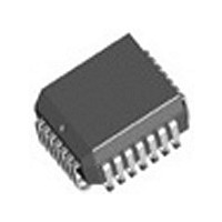
IDT82V1671J IDT, Integrated Device Technology Inc, IDT82V1671J Datasheet - Page 89

IDT82V1671J
Manufacturer Part Number
IDT82V1671J
Description
Manufacturer
IDT, Integrated Device Technology Inc
Datasheet
1.IDT82V1671J.pdf
(107 pages)
Specifications of IDT82V1671J
Number Of Channels
4
On-hook Transmission
Yes
Polarity Reversal
Yes
On-chip Ring Relay Driver
Yes
Operating Supply Voltage (typ)
3.3V
Operating Temp Range
-40C to 85C
Package Type
PLCC
Operating Temperature Classification
Industrial
Pin Count
28
Mounting
Surface Mount
Operating Current
95mA
Operating Supply Voltage (max)
3.465V
Operating Supply Voltage (min)
3.135V
Lead Free Status / RoHS Status
Not Compliant
Available stocks
Company
Part Number
Manufacturer
Quantity
Price
Company:
Part Number:
IDT82V1671J
Manufacturer:
BROADCOM
Quantity:
457
Part Number:
IDT82V1671J
Manufacturer:
IDT
Quantity:
20 000
6.1.2
Table -
LREG6 (MPI mode) or in the downstream C/I channel (GCI mode).
(GCI mode) determines whether the corresponding RSLIC will be
accessed. If this bit is set to 1, the RSLIC will receive data from the
CODEC when the corresponding CSn pin is logic low and transmit data
to the CODEC when the corresponding CSn pin is logic high (as
illustrated in
will be set to 1.5 V and the RSLIC will not be accessed.
Table - 26 RSLIC Operating Mode
transferred via the telephone line. Besides providing low-impedance
voltage (VBL) feeding to the line, the RSLIC senses, scales and
separates transversal and longitudinal line currents.
and RSN and feeds it to the telephone line. The RSLIC also provides a
ring trip signal for the CODEC via the RT pin.
the RSLIC through the DCP and DCN pins. The RSLIC amplifies this
ringing signal and feeds it to the telephone line.
ring terminal presents a high impedance to the line. This mode is used to
measure the leakage current Tip/GND.
terminal presents a high impedance to the line. This mode is used for
ground-key detection and the leakage current Ring/GND measurement.
external circuits.
as normal active mode. The only difference is that a built-in resistor will
be connected between the TIP and RING pins to form a loop for testing.
See
Normal Active
External Ring
Internal Ring
Ring Open
Tip Open
Internal Test
Low Power Standby
Power Down
Overtemp Check (read)
RSLIC & CODEC CHIPSET
The RSLICs can be operated in nine different modes as shown in
The SCAN_EN bit in LREG6 (MPI mode) or downstream C/I channel
• Normal Active
In this mode, a regular call can be performed. Voice can be
• External Ring
The RSLIC receives an external ringing signal provided at pins RSP
• Internal Ring
The CODEC generates a balanced ringing signal and outputs it to
• Ring Open
In ring open mode, the ring power amplifier is switched off and the
• Tip Open
In tip open mode, the tip power amplifier is switched off and the tip
• Internal Test
This mode can be used to test the RSLIC-CODEC chipset without
When the RSLIC is set to internal test mode, it works in a similar way
RSLIC Operating Mode
Figure - 40
26. The operating mode is configured by the SM[2:0] bits in
Figure -
RSLIC OPERATING MODES
for details.
39). If this bit is set to 0, the corresponding CSn pin
CS
0
0
0
0
0
0
0
0
1
RSLIC Mode Control Pins
M3
X
0
0
0
0
1
1
1
1
M2
0
0
1
1
0
0
1
1
1
M1
0
1
0
1
0
1
0
1
1
89
to reduce power consumption. Two 2.5 kΩ resistors are connected from
TIP to BGND and from RING to VBAT respectively. A simple sense
circuit monitors the DC current flowing through these resistors. By
calculating the transversal DC current and feeding it to the CODEC, off-
hook can be detected. Once the subscriber goes off-hook, the whole
chipset should be activated and put into active mode.
detection. The tip and ring power amplifiers are both switched off so that
the power consumption is minimal.
the CODEC through the M3 pin. This temperature state will be indicated
by the OTMP bit in LREG21. If the temperature exceeds the limit
(150
OTMP bit changes from 0 to 1, representing the temperature of the
RSLIC becoming overloaded, an interrupt will be generated if the OTMP
bit is not masked by the OTMP_M bit in LREG18.
6.1.3
Ramp and Ring. These modes are enabled by setting the P_DOWN,
STANDBY, ACTIVE and RAMP bits in LREG6 and RING bit in LREG7
respectively.
mode, all functions of the CODEC are switched off so that the power
dissipation can be minimized. Both AC and DC loops are inactive, no
current is fed to the line and the hook switch can not be detected.
setting the P_DOWN bit in corresponding LREG6. If four channels are
powered down, the clock cycles fed to the MCLK and BCLK pins should
be shut off to achieve the lowest power consumption.
modes by properly setting LREG6 and LREG7.
• Low Power Standby
In this mode, all functions except off-hook detection are switched off
• Power Down
In this mode, all functions are disabled, including the off-hook
• Overtemp Check
In this mode, the RSLIC will report the temperature state of itself to
The CODEC can work in five modes: Power Down, Standby, Active,
• Power Down
This mode is applicable for the line (channel) that is not in use. In this
Each channel of the CODEC can be powered down individually by
The CODEC can be changed from Power Down mode to any other
o
C), the RSLIC will be automatically shut down. Every time the
CODEC OPERATING MODES
Figure - 40 RSLIC Internal Test Circuit
R
R
S
S
IDT82V1671/IDT82V1671A, IDT82V1074
TIS
TIP
RING
RIS
2 k
RSLIC


