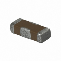
CKD510JB1H222S TDK Corporation, CKD510JB1H222S Datasheet - Page 3

CKD510JB1H222S
Manufacturer Part Number
CKD510JB1H222S
Description
CAP FEEDTHRU 2200PF 50V 0805
Manufacturer
TDK Corporation
Series
CKDr
Specifications of CKD510JB1H222S
Capacitance
2200pF
Voltage
50V
Current
400mA
Dc Resistance (dcr)
500.0 mOhm Max
Package / Case
0805 (2012 Metric)
Voltage Rating
50 Volts
Operating Temperature Range
- 55 C to + 85 C
Product
General Type MLCCs
Dimensions
1.25 mm W x 2 mm L
Termination Style
SMD/SMT
Tolerance
- 20 %, 50 %
Lead Free Status / RoHS Status
Lead free / RoHS Compliant
Operating Temperature
-
Lead Free Status / Rohs Status
Lead free / RoHS Compliant
Other names
445-3017-2
Available stocks
Company
Part Number
Manufacturer
Quantity
Price
Part Number:
CKD510JB1H222ST
Manufacturer:
TDK/东电化
Quantity:
20 000
3-terminal Feed Through Multilayer Ceramic Chip Capacitors
CKD Series
FEATURES
• These small low-cost filters are used for meeting EMC
• Can be used up to even higher frequencies due to low parasitic
• Optimized for use as a noise bypass capacitors for signal and
APPLICATIONS
For digital and analog signal line noise bypassing signal line
PRODUCT IDENTIFICATION
(1) Series name
CKD110JB
CKD310JB
CKD510JB
CKD610JB
CKD61BJB
(2) Rated voltage Edc
0J
1A
1C
1E
1H
(3) Nominal capacitance
The capacitance is expressed in three digit codes and in units of
pico farads (pF).
The first and second digits identify the first and second significant
figures of the capacitance.
The third digit identifies the multiplier.
R designates a decimal point.
220
101
222
473
(4) Capacitance tolerance
S
(5) Packaging style
T
B
• Conformity to RoHS Directive: This means that, in conformity with EU Directive 2002/95/EC, lead, cadmium, mercury, hexavalent chromium, and specific
• All specifications are subject to change without notice.
Please read the precautions before using this catalog.
CKD510JB 1H 220 S
bromine-based flame retardants, PBB and PBDE, have not been used, except for exempted applications.
requirements.
inductance.
power source circuits.
(1)
(2) (3) (4) (5)
3.20× 1.25× 0.85mm
3.20× 1.60× 1.30mm
2.00× 1.25× 0.85mm
1.60× 0.80× 0.80mm
1.60× 0.80× 0.60mm
6.3V
10V
16V
25V
50V
22pF
100pF
2,200pF
47,000pF
+50, –20%
Taping (reel)
Bulk
SHAPES AND DIMENSIONS
CKD110/310/510/610JB
Type
CKD110JB
CKD310JB
CKD510JB
CKD610JB
CIRCUIT DIAGRAM
IN
• No polarity
GND
GND
L
3.20
3.20
2.00
1.60
L
W
1.25
1.60
1.25
0.80
OUT
T
0.85
1.30
0.85
0.80
CKD61BJB
Conformity to RoHS Directive
004-01 / 20080603 / e4161_ckd.fm
0.15±0.1
1.60±0.1
0.80
Dimensions in mm
+0.2
–0.1
0.15±0.1
(2/4)


