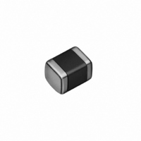
FBMJ2125HS420-T Taiyo Yuden, FBMJ2125HS420-T Datasheet - Page 12

FBMJ2125HS420-T
Manufacturer Part Number
FBMJ2125HS420-T
Description
FERRITE BEAD 42 OHM 0805
Manufacturer
Taiyo Yuden
Series
FBr
Datasheet
1.FBMJ1608HM230NT.pdf
(14 pages)
Specifications of FBMJ2125HS420-T
Impedance @ Frequency
42 Ohm @ 100MHz
Current Rating
4A
Dc Resistance (dcr)
8.000 mOhm Max
Filter Type
Differential Mode - Single
Number Of Lines
1
Package / Case
0805 (2012 Metric)
Mounting Type
Surface Mount
Lead Free Status / RoHS Status
Lead free / RoHS Compliant
Other names
587-1768-2
FBMJ2125HS420-T
FBMJ2125HS420-T
Available stocks
Company
Part Number
Manufacturer
Quantity
Price
Company:
Part Number:
FBMJ2125HS420-T
Manufacturer:
TAIYO
Quantity:
460 000
Company:
Part Number:
FBMJ2125HS420-T
Manufacturer:
Taiyo Yuden
Quantity:
83 210
Part Number:
FBMJ2125HS420-T
Manufacturer:
TAIYO/太诱
Quantity:
20 000
RECTANGULAR FERRITE CHIP BEADS (HIGH CURRENT) FB series M type
Note on standard condition: "standard condition" referred to herein is defined as follows 5 to 35℃ of temperature, 45 to 85% relative humidity and 86 to 106kPa of air pressure.
When there are questions concerning measurement results: In order to provide correlation data, the test shall be conducted under condition of 20±2℃ of temperature, 60 to 70% relative humidity
△
1.Operating Temperature Range
2.Storage Temperature Range
3.Impedance
4. DC Resistance
5.Rated Current
6.Vibration
7. Solderability
8.Resistance to Solder Heat
9.Thermal Shock
10.Humidity (steady state)
11.Loading under Damp Heat
12.High Temperature Loading
13.Resistance to Flexure of
14.Adhesion of Electrode
!
RELIABILITY DATA
当社カタログをご使用の際には 「当社製品に関するお断り」 を必ずお読みください。
Test
Substrate
Item
ー40∼+85℃
ー40∼+85℃
Within the specified tolerance
Within the specified range
Within the specified range
Appearance: No significant abnormality
Impedance change: Within ±30% of the initial value
75% or more of immersed surface of terminal electrode shall be covered
with fresh solder.
Appearance: No significant abnormality
Impedance change: Within ±30% of the initial value
Appearance: No significant abnormality
Impedance change: Within % of the initial value
Appearances: No significant abnormality
Impedance change: Within ±30% of the initial value
Appearance : No significant abnormality
Impedance change : Within ±30% of the initial value
Appearance: No significant abnormality
Impedance change: Within ±30% of the initial value
No mechanical damage.
No separation or indication of separation of electrode.
and 86 to 106kPa of air pressure.
Unless otherwise specified, all the tests are conducted under the "standard condition."
+50
ー10
Specified Value
*Note: 0 to +40℃ in taped packaging
Measuring equipment: Impedance analyzer (HP4291A) or its equivalent
Measuring frequency: 100±1 MHZ
Four-terminal method
Measuring equipment: Milliohm High-Tester 3226 ( Hioki Denki) or its equivalent
According to JIS C 0040.
Vibration type: A
Directions: 2 hrs each in X,Y, and Z directions
Frequency range: 10 to 55 to 10Hz ( /min.)
Amplitude: 1.5 mm (shall not exceed acceleration 196m/s
Mounting method: Soldering onto PC board
Solder temperature: 230±5℃
Duration: 4±1 sec.
Preconditioning: Immersion into flux.
Immersion and Removal speed: 25mm/sec.
Preheating: 150℃ for 3 min.
Solder temperature: 260±5℃
Duration: 10±0.5sec
Preconditioning: Immersion into flux.
Immersion and Removal speed: 25 mm/sec.
Recovery: 2 to 3 hrs of recovery under the standard condition after the test.
According to JIS C 0025.
Conditions for 1 cycle
Number of cycles: 100
Mounting method: Soldering onto PC board
Recovery: 2 to 3 hrs of recovery under the standard condition after the removal
Temperature: 40±2˚C
Humidity: 90 to 95%RH
Duration: 500
Mounting method: Soldering onto PC board
Recovery: 2 to 3 hrs of recovery under the standard condition after the removal
Temperature : 40±2˚C
Humidity : 90 to 95%RH
Applied current : Rated current
Duration : 500
Mounting method : Soldering onto PC board
Recovery : 2 to 3hrs of recovery under the standard condition after the removal
Temperature: 85±2℃
Duration: 500
Applied current: Rated current
Mounting method: Soldering onto PC board
Recovery: 2 to 3 hrs of recovery under the standard condition after the removal
Warp: 2mm
Testing board: Glass epoxy-resin substrate
Thickness: 0.8mm
Applied force: 5N
Duration: 10 sec.
Step
1
2
3
4
Room Temperature
Room Temperature
Temperature ( ℃)
from test chamber.
from test chamber.
from test chamber.
from test chamber.
△
!
ー40±3℃
ー85±2℃
+24
ー 0
+24
ー 0
+24
ー 0
Please read the "Notice for TAIYO YUDEN products" before using this catalog.
hrs
hrs
hrs
Test Methods and Remarks
Duration ( min.)
Within 3
Within 3
30±3
30±3
Total: 6 hrs
2
)
279
5


