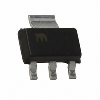
MIC5239-1.8YS TR Micrel Inc, MIC5239-1.8YS TR Datasheet - Page 11

MIC5239-1.8YS TR
Manufacturer Part Number
MIC5239-1.8YS TR
Description
High Vin, Low Iq Regulator ( )
Manufacturer
Micrel Inc
Datasheet
1.MIC5239YM.pdf
(14 pages)
Specifications of MIC5239-1.8YS TR
Regulator Topology
Positive Fixed
Voltage - Output
1.8V
Voltage - Input
2.3 ~ 30 V
Voltage - Dropout (typical)
0.35V @ 500mA
Number Of Regulators
1
Current - Output
500mA
Operating Temperature
-40°C ~ 125°C
Mounting Type
Surface Mount
Package / Case
SOT-223 (3 leads + Tab), SC-73, TO-261
Voltage Regulator Type
Linear
Topology
LDO
Regulator Output Type
Fixed
Polarity Type
Positive
Number Of Outputs
Single
Input Voltage (min)
2.3V
Input Voltage (max)
30V
Output Voltage
1.8V
Package Type
SOT-223
Output Current
500mA
Load Regulation
30mV
Line Regulation
0.5%
Output Voltage Accuracy
±1%
Operating Temp Range
-40C to 125C
Operating Temperature Classification
Automotive
Dropout Voltage@current (max)
0.35@150uA
Dropout Voltage@current (typ)
0.05@100uA
Pin Count
3 +Tab
Mounting
Surface Mount
Lead Free Status / RoHS Status
Lead free / RoHS Compliant
Current - Limit (min)
-
Lead Free Status / Rohs Status
Compliant
Other names
MIC5239-1.8YSTR
MIC5239-1.8YSTR
MIC5239-1.8YSTR
For example, the maximum ambient temperature is
50°C, the ∆T is determined as follows:
Using Figure 6, the minimum amount of required copper
can be determined based on the required power
dissipation. Power dissipation in a linear regulator is
calculated as follows:
If we use a 3V output device and a 28V input at
moderate output current of 25mA, then our power
dissipation is as follows:
From Figure 6, the minimum amount of copper required
to operate this application at a ∆T of 75°C is 110mm
Quick Method
Determine the power dissipation requirements for the
design along with the maximum ambient temperature at
which the device will be operated. Refer to Figure 7,
which shows safe operating curves for three different
ambient temperatures: 25°C, 50°C and 85°C. From
these curves, the minimum amount of copper can be
determined by knowing the maximum power dissipation
required. If the maximum ambient temperature is 50°C
and the power dissipation is as above, 639mW, the
curve in Figure 7 shows that the required area of copper
is 110mm
The θ
depending upon the availability of copper ground plane
to which it is attached.
Micrel
December 2007
∆T = T
T
T
∆T = 125°C – 50°C
∆T = 75°C
P
P
P
P
J
A
D
D
D
D
JA
(max) = 125°C
(max) = maximum ambient operating
= (V
= (28V – 3V) × 25mA + 28V 250µA
= 625mW + 7mW
= 632mW
of this package is ideally 80°C/W, but it will vary
Figure 7. Copper Area vs. Power-MSOP
2
.
J
IN
(max) – T
– V
temperature
OUT
Power Dissipation (T
) I
A
OUT
(max)
+ V
IN
× I
GND
A
)
2
.
11
The same method of determining the heatsink area used
for the power MSOP-8 can be applied directly to the
power SOIC-8. The same two curves showing power
dissipation versus copper area are reproduced for the
power SOIC-8 and they can be applied identically.
Power SOIC-8 Thermal Characteristics
The power SOIC-8 package follows the same idea as
the power MSOP-8 package, using four ground leads
with the die attach paddle to create a single-piece
electrical and thermal conductor, reducing thermal
resistance and increasing power dissipation capability.
Quick Method
Determine the power dissipation requirements for the
design along with the maximum ambient temperature at
which the device will be operated. Refer to Figure 9,
which shows safe operating curves for three different
ambient temperatures, 25°C, 50°C, and 85°C. From
these curves, the minimum amount of copper can be
determined by knowing the maximum power dissipation
required. If the maximum ambient temperature is 50°C,
and the power dissipation is 632mW, the curve in Figure
9 shows that the required area of copper is less than
100mm
2
, when using the power SOIC-8.
Figure 8. Copper Area vs. Power-SOIC
Figure 9. Copper Area vs. Power-SOIC
Power Dissipation (∆T
Power Dissipation (T
A
JA
)
)
M9999-121007
MIC5239


