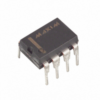
DS1678+ Maxim Integrated Products, DS1678+ Datasheet - Page 6

DS1678+
Manufacturer Part Number
DS1678+
Description
IC REAL TIME EVENT REC 8-DIP
Manufacturer
Maxim Integrated Products
Type
Time Event Recorderr
Datasheet
1.DS1678STR.pdf
(25 pages)
Specifications of DS1678+
Memory Size
32B
Time Format
HH:MM:SS (12/24 hr)
Date Format
YY-MM-DD-dd
Interface
I²C, 2-Wire Serial
Voltage - Supply
4.5 V ~ 5.5 V
Operating Temperature
-40°C ~ 85°C
Mounting Type
Through Hole
Package / Case
8-DIP (0.300", 7.62mm)
Lead Free Status / RoHS Status
Lead free / RoHS Compliant
PIN DESCRIPTION
PIN NAME
1, 2
3
4
5
6
7
8
X1, X2
GND
V
SDA
SCL
INT
V
BAT
CC
Connections for Standard 32.768kHz Quartz Crystal. For greatest accuracy,
the DS1678 must be used with a crystal that has a specified load capacitance
of 12.5pF. There is no need for external capacitors or resistors. Note: X1 and
X2 are very high-impedance nodes. It is recommended that they and the
crystal be isolated from high-frequency signals. For more information on
crystal selection and crystal layout considerations, refer to Application Note
58: Crystal Considerations with Dallas Real-Time Clocks.
Battery Input for Standard Lithium Cell or Other Energy Source. All
functions of the DS1678 with the exception of the serial interface circuitry
are powered by V
when V
a battery or other energy source is not used, V
directly to ground. Diodes must not be placed between the battery and the
V
reverse charging current when used with a lithium battery. See “Conditions
of Acceptability” at www.maxim-ic.com/qa/info/ul/.
Ground
Serial Data Input/Output. SDA is the data input/output (I/O) signal for the
I
external pullup resistor.
Serial Clock Input. SCL is used to synchronize data movement on the serial
interface. It requires an external pullup resistor.
Active-Low Interrupt Input/Output. The INT pin is an I/O that is activated by
an external device to signify an event has occurred and should be logged.
Once the pin is activated, the event is recorded in the event-log memory and
the Event Counter Register is incremented. The TRx bits determine which
input edge(s) trigger an event: An event can be triggered by a falling edge on
the INT pin, a rising edge, or by both the rising and falling edges.
The INT pin can also be used as an output when the DS1678 is not in an
event-logging mission. The INT pin becomes an output and generates an
alarm interrupt if the DISx bits are set to zero and the RTC reaches the preset
value in the alarm register. The INT output remains low as long as the status
bit causing the interrupt is present and the DISx bits are set to zero.
The INT pin is an open-drain input/output with a weak internal pulldown
resistor to prevent the pin from floating when the pin is tri-stated.
DC Power for Primary Power Supply
2
C serial interface. The SDA pin is an open-drain I/O and requires an
BAT
input or improper operation results. UL recognized to ensure against
CC
> V
BAT
BAT
. The serial interface is enabled when V
when V
6 of 25
CC
FUNCTION
< V
BAT
. All functions are powered by V
BAT
should be connected
CC
is above V
PF
CC
. If


