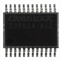
CS5524-ASZ Cirrus Logic Inc, CS5524-ASZ Datasheet - Page 18

CS5524-ASZ
Manufacturer Part Number
CS5524-ASZ
Description
IC ADC 24BIT 4CH 20SSOP
Manufacturer
Cirrus Logic Inc
Specifications of CS5524-ASZ
Number Of Converters
1
Package / Case
24-SSOP
Number Of Bits
24
Data Interface
Serial
Power Dissipation (max)
14.8mW
Voltage Supply Source
Analog and Digital
Operating Temperature
-40°C ~ 85°C
Mounting Type
Surface Mount
Number Of Adc Inputs
4
Architecture
Delta-Sigma
Conversion Rate
617 SPs
Resolution
24 bit
Input Type
Voltage
Interface Type
Serial (3-Wire)
Voltage Reference
2.5 V
Supply Voltage (max)
5 V
Supply Voltage (min)
25 mV
Maximum Power Dissipation
500 mW
Maximum Operating Temperature
+ 85 C
Mounting Style
SMD/SMT
Input Voltage
25 mV to 5 V
Minimum Operating Temperature
- 40 C
Lead Free Status / RoHS Status
Lead free / RoHS Compliant
For Use With
598-1012 - EVAL BOARD FOR CS5524 ADC
Lead Free Status / Rohs Status
Lead free / RoHS Compliant
Other names
598-1106-5
Available stocks
Company
Part Number
Manufacturer
Quantity
Price
Part Number:
CS5524-ASZ
Manufacturer:
CIRRUS
Quantity:
20 000
2.2.1 System Initialization
When power to the CS5521/22/23/24/28 is applied,
the chips are held in a reset condition until the
32.768 kHz oscillator has started and a counter-
timer elapses. Due to the high Q of the 32.768 kHz
crystal, the oscillator takes 400-600 ms to start. The
counter-timer counts 2006 oscillator clock cycles
to make sure the oscillator is fully stable. During
this time-out period, the serial port logic is reset
and the RV (Reset Valid) bit in the configuration
register is set to indicate that a valid reset occurred.
After a reset, the on-chip registers are initialized to
the following states and the converter is placed in
the command mode where it waits for a valid com-
mand.
18
configuration register:
offset registers:
gain registers:
channel setup registers:
000040(H)
000000(H)
400000(H)
000000(H)
Note: A system reset can be initiated at any time by writing
2.2.2 Serial Port Initialization Sequence
The serial port is initialized to the command mode
whenever a power-on reset is performed inside the
converter, or when the user transmits the port ini-
tialization sequence. The port initialization se-
quence involves clocking 15 bytes of all 1's,
followed by one byte with the following bit con-
tents ‘1111 1110’. This sequence places the chip in
the command mode where it waits for a valid com-
mand to be written.
a logic 1 to the RS (Reset System) bit in the configura-
tion register. After a reset, the RV bit is set until the
configuration register is read. The user must then
write a logic 0 to the RS bit to take the part out of the
reset mode. Any other bits written to the configuration
register at this time will be lost. The configuration reg-
ister must be written again once RS = 0 to set any other
bits.
CS5521/22/23/24/28
DS317F4


