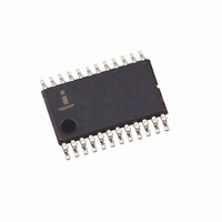
X9400WV24I Intersil, X9400WV24I Datasheet - Page 13

X9400WV24I
Manufacturer Part Number
X9400WV24I
Description
IC DCP QUAD 10K 64TP 24TSSOP
Manufacturer
Intersil
Series
XDCP™r
Datasheet
1.X9400WV24-2.7.pdf
(19 pages)
Specifications of X9400WV24I
Taps
64
Resistance (ohms)
10K
Number Of Circuits
4
Temperature Coefficient
300 ppm/°C Typical
Memory Type
Non-Volatile
Interface
SPI, 3-Wire Serial
Voltage - Supply
4.5 V ~ 5.5 V
Operating Temperature
-40°C ~ 85°C
Mounting Type
Surface Mount
Package / Case
24-TSSOP
Resistance In Ohms
10K
Lead Free Status / RoHS Status
Contains lead / RoHS non-compliant
A.C. TEST CONDITIONS
Notes: (4) This parameter is periodically sampled and not 100% tested
SPICE Macro Model
AC TIMING
I nput pulse levels
Input rise and fall times
Input and output timing level
Symbol
t
WPASU
t
t
t
WPAH
HOLD
f
t
t
LEAD
t
t
t
CYC
t
t
t
HSU
SCK
LAG
t
t
t
t
t
WH
DIS
t
t
WL
SU
t
HO
RO
FO
HH
CS
t
t
HZ
T
LZ
RI
FI
H
V
(5) t
I
third (last) power supply (V
specific instruction can be issued. These parameters are
periodically sampled and not 100% tested.
PUR
R
H
and t
SSI/SPI clock frequency
SSI/SPI clock cycle time
SSI/SPI clock high time
SSI/SPI clock low time
Lead time
Lag time
SI, SCK, HOLD and CS input setup time
SI, SCK, HOLD and CS input hold time
SI, SCK, HOLD and CS input rise time
SI, SCK, HOLD and CS input fall time
SO output disable time
SO output valid time
SO output hold time
SO output rise time
SO output fall time
HOLD time
HOLD setup time
HOLD hold time
HOLD low to output in High Z
HOLD high to output in Low Z
Noise suppression time constant at SI, SCK, HOLD and CS inputs
CS deselect time
WP, A0 and A1 setup time
WP, A0 and A1 hold time
10pF
PUW
C
H
are the delays required from the time the
R
TOTAL
13
R
W
25pF
C
CC
W
V
10ns
V
, V+ or V-) is stable until the
CC
CC
10pF
C
x 0.1 to V
x 0.5
L
Parameter
R
L
CC
x 0.9
X9400
SYMBOL TABLE
WAVEFORM
INPUTS
Must be
steady
May change
from Low to
High
May change
from High to
Low
Don’t Care:
Changes
Allowed
N/A
Min.
500
200
200
250
250
400
100
100
50
50
2
0
0
0
0
Will be
steady
Will change
from Low to
High
Will change
from High to
Low
Changing:
State Not
Known
Center Line
is High
Impedance
OUTPUTS
Max.
500
100
100
100
2.0
50
50
20
2
2
July 28, 2006
Unit
MHz
ns
ns
ns
ns
µs
ns
ns
ns
ns
ns
ns
µs
ns
ns
ns
ns
µs
ns
ns
ns
ns
ns
ns
FN8189.3


