MCP4017T-503E/LT Microchip Technology, MCP4017T-503E/LT Datasheet - Page 47
MCP4017T-503E/LT
Manufacturer Part Number
MCP4017T-503E/LT
Description
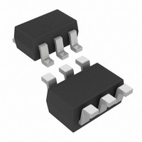
IC DGTL POT 50K 128TAPS SC70-6
Manufacturer
Microchip Technology
Datasheet
1.MCP4018T-502ELT.pdf
(66 pages)
Specifications of MCP4017T-503E/LT
Package / Case
SC-70-6, SC-88, SOT-363
Temperature Coefficient
150 ppm/°C Typical
Taps
128
Resistance (ohms)
50K
Number Of Circuits
1
Memory Type
Volatile
Interface
I²C, 2-Wire Serial
Voltage - Supply
1.8 V ~ 5.5 V
Operating Temperature
-40°C ~ 125°C
Mounting Type
Surface Mount
Resistance In Ohms
50K
Number Of Pots
Single
Taps Per Pot
128
Resistance
50 KOhms
Wiper Memory
Volatile
Buffered Wiper
Buffered
Digital Interface
Serial (2-Wire, I2C)
Operating Supply Voltage
2.5 V or 3.3 V or 5 V
Supply Current
0.045 mA (Typ)
Maximum Operating Temperature
+ 125 C
Minimum Operating Temperature
- 40 C
Description/function
7 Bit Single I2C Digital Rheostat
Mounting Style
SMD/SMT
Supply Voltage (max)
5.5 V
Supply Voltage (min)
1.8 V
Tolerance
20 %
End To End Resistance
50kohm
Track Taper
Linear
No. Of Steps
128
Resistance Tolerance
± 20%
Supply Voltage Range
1.8V To 5.5V
Control Interface
I2C
No. Of Pots
Single
Rohs Compliant
No
Lead Free Status / RoHS Status
Lead free / RoHS Compliant
Lead Free Status / RoHS Status
Lead free / RoHS Compliant, Lead free / RoHS Compliant
Other names
MCP4017T-503E/LTTR
Available stocks
Company
Part Number
Manufacturer
Quantity
Price
Company:

Part Number:
MCP4017T-503E/LT
Manufacturer:
AMS
Quantity:
2 300
Part Number:
MCP4017T-503E/LT
Manufacturer:
MICROCHIP/微芯
Quantity:
20 000


7.0
In the design of a system with the MCP4017/18/19
devices, the following considerations should be taken
into account. These are:
• The Power Supply
• The Layout
In the design of a system with the MCP4017/18/19
devices, the following considerations should be taken
into account:
•
•
7.1
The typical application will require a bypass capacitor
in order to filter high-frequency noise, which can be
induced onto the power supply's traces. The bypass
capacitor helps to minimize the effect of these noise
sources on signal integrity.
appropriate bypass strategy.
In this example, the recommended bypass capacitor
value is 0.1 µF. This capacitor should be placed as
close to the device power pin (V
4 mm).
The power source supplying these devices should be
as clean as possible. If the application circuit has
separate digital and analog power supplies, V
V
FIGURE 7-1:
Connections.
© 2009 Microchip Technology Inc.
SS
Power Supply Considerations
Layout Considerations
should reside on the analog plane.
W
A
B
DESIGN CONSIDERATIONS
Power Supply Considerations
0.1 µF
V
V
DD
SS
Typical Microcontroller
Figure 7-1
DD
0.1 µF
SDA
SCL
) as possible (within
V
V
illustrates an
DD
SS
DD
and
7.2
Inductively-coupled AC transients and digital switching
noise can degrade the input and output signal integrity,
potentially
performance. Careful board layout will minimize these
effects and increase the Signal-to-Noise Ratio (SNR).
Bench testing has shown that a multi-layer board
utilizing a low-inductance ground plane, isolated inputs,
isolated outputs and proper decoupling are critical to
achieving the performance that the silicon is capable of
providing. Particularly harsh environments may require
shielding of critical signals.
If low noise is desired, breadboards and wire-wrapped
boards are not recommended.
7.2.1
Characterization curves of the resistor temperature
coefficient (Tempco) are shown in
Figure
These curves show that the resistor network is
designed to correct for the change in resistance as
temperature increases. This technique reduces the
end to end change is R
2-29,
Layout Considerations
RESISTOR TEMPCO
Figure
MCP4017/18/19
masking
2-47, and
AB
resistance.
the
Figure
MCP4017/18/19’s
DS22147A-page 47
2-65.
Figure
2-11,
Related parts for MCP4017T-503E/LT
Image
Part Number
Description
Manufacturer
Datasheet
Request
R

Part Number:
Description:
IC DGTL POT 5K 128TAPS SC70-6
Manufacturer:
Microchip Technology
Datasheet:
Part Number:
Description:
IC DGTL POT 100K 128TAPS SC70-6
Manufacturer:
Microchip Technology
Datasheet:
Part Number:
Description:
IC DGTL POT 10K 128TAPS SC70-6
Manufacturer:
Microchip Technology
Datasheet:

Part Number:
Description:
7-bit Single I 2 C? Digital Pot With Volatile Memory In Sc70
Manufacturer:
Microchip Technology Inc.
Datasheet:

Part Number:
Description:
(MCP4017 - MCP4019) 7-Bit Single I2C Digital POT
Manufacturer:
Microchip Technology
Part Number:
Description:
Manufacturer:
Microchip Technology Inc.
Datasheet:
Part Number:
Description:
Manufacturer:
Microchip Technology Inc.
Datasheet:
Part Number:
Description:
Manufacturer:
Microchip Technology Inc.
Datasheet:
Part Number:
Description:
Manufacturer:
Microchip Technology Inc.
Datasheet:
Part Number:
Description:
Manufacturer:
Microchip Technology Inc.
Datasheet:
Part Number:
Description:
Manufacturer:
Microchip Technology Inc.
Datasheet: