ADV7120KSTZ30 Analog Devices Inc, ADV7120KSTZ30 Datasheet
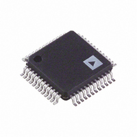
IC DAC VIDEO 3-CH 30MHZ 48-LQFP

ADV7120KSTZ30

Manufacturer Part Number
ADV7120KSTZ30
Description
IC DAC VIDEO 3-CH 30MHZ 48-LQFP
Manufacturer
Analog Devices Inc
Datasheet

Specifications of ADV7120KSTZ30

Data Interface
Parallel
Settling Time
12ns
Number Of Bits
8
Number Of Converters
3
Voltage Supply Source
Single Supply
Power Dissipation (max)
625mW
Operating Temperature
0°C ~ 70°C
Mounting Type
Surface Mount
Package / Case
48-LQFP
Resolution (bits)
8bit
Sampling Rate
80MSPS
Input Channel Type
Parallel
Supply Voltage Range - Analogue
4.75V To 5.25V
Supply Current
125mA
Digital Ic
RoHS Compliant
Lead Free Status / RoHS Status
Lead free / RoHS Compliant

Available stocks

Company
Part Number
Manufacturer
Quantity
Price
Part Number:
ADV7120KSTZ30
Manufacturer:
ADI
Quantity:
212
Part Number:
ADV7120KSTZ30
Manufacturer:
Analog Devices Inc
Quantity:
10 000
Part Number:
ADV7120KSTZ30-REEL
Manufacturer:
Analog Devices Inc
Quantity:
10 000
a
GENERAL DESCRIPTION
The ADV7120 (ADV ) is a digital to analog video converter on
a single monolithic chip. The part is specifically designed for
high resolution color graphics and video systems. It is also ideal
for any high speed communications type applications requiring
low cost, high speed DACs. It consists of three, high speed,
8-bit, video D/A converters (RGB); a standard TTL input inter-
face and high impedance, analog output, current sources.
The ADV7120 has three separate, 8-bit, pixel input ports, one
each for red, green and blue video data. Additional video input
controls on the part include composite sync, blank and refer-
ence white. A single +5 V supply, an external 1.23 V reference
and pixel clock input are all that are required to make the part
operational.
The ADV7120 is capable of generating RGB video output sig-
nals, which are compatible with RS-343A and RS-170 video
standards, without requiring external buffering.
The ADV7120 is fabricated in a +5 V CMOS process. Its
monolithic CMOS construction ensures greater functionality
with low power dissipation. The part is packaged in both a 0.6",
40-pin plastic DIP and a 44-pin plastic leaded (J-lead) chip car-
rier, PLCC. The ADV7120 is also available in a very small 48-
lead Thin Quad Flatpack (TQFP).
ADV is a registered trademark of Analog Devices, Inc.
*Speed grades up to 140 MHz are also available upon special request.
REV. B
Information furnished by Analog Devices is believed to be accurate and
reliable. However, no responsibility is assumed by Analog Devices for its
use, nor for any infringements of patents or other rights of third parties
which may result from its use. No license is granted by implication or
otherwise under any patent or patent rights of Analog Devices.
Please contact Analog Devices or its representatives for further details.
FEATURES
80 MHz Pipelined Operation
Triple 8-Bit D/A Converters
RS-343A/RS-170 Compatible Outputs
TTL Compatible Inputs
+5 V CMOS Monolithic Construction
40-Pin DIP or 44-Pin PLCC and 48-Lead TQFP
APPLICATIONS
High Resolution Color Graphics
CAE/CAD/CAM Applications
Image Processing
Instrumentation
Video Signal Reconstruction
Desktop Publishing
Direct Digital Synthesis (DDS) and I/Q Modulation
SPEED GRADES*
80 MHz
50 MHz
30 MHz
PRODUCT HIGHLIGHTS
1. Fast video refresh rate, 80 MHz.
2. Compatible with a wide variety of high resolution color
3. Guaranteed monotonic with a maximum differential non-
One Technology Way, P.O. Box 9106, Norwood, MA 02062-9106, U.S.A.
Tel: 617/329-4700
INPUT
PIXEL
PORT
REF WHITE
80 MHz, Triple 8-Bit Video DAC
graphics video systems.
linearity of 0.5 LSB. Integral nonlinearity is guaranteed to
be a maximum of 1 LSB.
CLOCK
BLANK
SYNC
G0
G7
R0
R7
B0
B7
FUNCTIONAL BLOCK DIAGRAM
GND
V
AA
ADV7120
8
8
8
REGISTER
REGISTER
REGISTER
REGISTER
CONTROL
ADJUST
GREEN
BLUE
RED
FS
8
8
8
V
REF
ADV7120
CONTROL
DAC
DAC
DAC
SYNC
REFERENCE
AMPLIFIER
Fax: 617/326-8703
CMOS
COMP
IOR
IOG
IOB
I
SYNC

Related parts for ADV7120KSTZ30

ADV7120KSTZ30 Summary of contents

Page 1

FEATURES 80 MHz Pipelined Operation Triple 8-Bit D/A Converters RS-343A/RS-170 Compatible Outputs TTL Compatible Inputs +5 V CMOS Monolithic Construction 40-Pin DIP or 44-Pin PLCC and 48-Lead TQFP APPLICATIONS High Resolution Color Graphics CAE/CAD/CAM Applications Image Processing Instrumentation Video ...

Page 2

ADV7120–SPECIFICATIONS Parameter STATIC PERFORMANCE Resolution (Each DAC) Accuracy (Each DAC) Integral Nonlinearity, INL Differential Nonlinearity, DNL Gray Scale Error Coding DIGITAL INPUTS Input High Voltage, V INH Input Low Voltage, V INL Input Current Input Capacitance, C ...

Page 3

TIMING CHARACTERISTICS Parameter 80 MHz Version 50 MHz Version MAX 12 ...

Page 4

ADV7120 RECOMMENDED OPERATING CONDITIONS Parameter Symbol Min Power Supply V 4.75 AA Ambient Operating Temperature Output Load R L Reference Voltage V 1.14 REF 1 ABSOLUTE MAXIMUM RATINGS V to GND . . . . . . ...

Page 5

Pin Mnemonic Function BLANK Composite blank control input (TTL compatible). A logic zero on this control input drives the analog out- puts, IOR, IOB and IOG, to the blanking level. The BLANK signal is latched on the rising edge of ...

Page 6

ADV7120 TERMINOLOGY Blanking Level The level separating the SYNC portion from the video portion of the waveform. Usually referred to as the front porch or back porch IRE units the level which will shut off the ...

Page 7

If we, therefore, have a graphics system with a 1024 1024 resolution, a noninterlaced 60 Hz refresh rate and a retrace fac- tor of 0.8, then: Dot Rate = 1024 1024 60/0.8 = 78.6 MHz RED, BLUE GREEN mA V ...

Page 8

ADV7120 A resistance R connected between FS ADJUST and GND SET determines the amplitude of the output video level according to the following equations: IOG (mA) = 12,082 V (V)/R REF SET IOR, IOB (mA) = 8,628 V (V)/R REF ...

Page 9

The unused analog outputs should be terminated with the same load as that for the used channel. In other words, if the red channel is used and IOR is terminated with a doubly terminated 75 load (37.5 ), IOB and ...

Page 10

ADV7120 PC BOARD LAYOUT CONSIDERATIONS The ADV7120 is optimally designed for lowest noise perfor- mance, both radiated and conducted noise. To complement the excellent noise performance of the ADV7120 imperative that great care be given to the PC ...

Page 11

Power Planes The PC board layout should have two distinct power planes, one for analog circuitry and one for digital circuitry. The analog power plane should encompass the ADV7120 (V sociated analog circuitry. This power plane should be connected to ...

Page 12

ADV7120 0.045 TYP 0.17 (4.32) MAX 0.021 (0.533) 0.015 (0.381) 0.004 OUTLINE DIMENSIONS Dimensions shown in inches and (mm). 44-Terminal Plastic Leaded Chip Carrier (P-44A) 0.045 TYP 0.045 TYP PIN 1 IDENTIFIER 0.045 ...

Related keywords