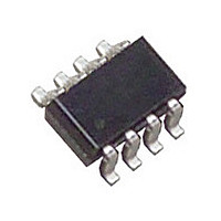
LT3092ITS8#PBF Linear Technology, LT3092ITS8#PBF Datasheet - Page 13

LT3092ITS8#PBF
Manufacturer Part Number
LT3092ITS8#PBF
Description
Manufacturer
Linear Technology
Datasheet
1.LT3092ITS8PBF.pdf
(22 pages)
Specifications of LT3092ITS8#PBF
Operating Temperature (max)
125C
Operating Temperature (min)
-40C
Pin Count
8
Mounting
Surface Mount
Package Type
TSOT-23
Case Length
2.9mm
Screening Level
Automotive
Lead Free Status / Rohs Status
Compliant
Available stocks
Company
Part Number
Manufacturer
Quantity
Price
interface, heat sink resistance or circuit board-to-ambient
as the application dictates. Consider all additional, adjacent
heat generating sources in proximity on the PCB.
Surface mount packages provide the necessary heat
sinking by using the heat spreading capabilities of the
PC board, copper traces and planes. Surface mount heat
sinks, plated through-holes and solder fi lled vias can also
spread the heat generated by power devices.
Junction-to-case thermal resistance is specifi ed from the
IC junction to the bottom of the case directly, or the bottom
of the pin most directly, in the heat path. This is the lowest
thermal resistance path for heat fl ow. Only proper device
mounting ensures the best possible thermal fl ow from this
area of the package to the heat sinking material.
APPLICATIONS INFORMATION
1V
LT3092
LT3092
3092 F09
SET
SET
20k
50k
10μA
10μA
Figure 8. Connect Two LT3092s for Higher Current
+
–
+
–
IN
IN
OUT
OUT
Figure 9. Parallel Devices
I
OUT
40mΩ*
I
OUT
I
300Ω
1.33Ω
OUT
, 400mA
I
, 300mA
OUT
LT3092
Note that the Exposed Pad of the DFN package and the
Tab of the SOT-223 package are electrically connected
to the output (V
The following tables list thermal resistance as a function
of copper areas in a fi xed board size. All measurements
were taken in still air on a four-layer FR-4 board with 1oz
solid internal planes and 2oz external trace planes with a
total fi nished board thickness of 1.6mm.
PCB layers, copper weight, board layout and thermal vias
affect the resultant thermal resistance. Please reference
JEDEC standard JESD51-7 for further information on high
thermal conductivity test boards. Achieving low thermal
resistance necessitates attention to detail and careful layout.
300Ω
1.33Ω
SET
10μA
LT3092
OUT
OUT
+
–
IN
*40mΩ PC BOARD TRACE
OUT
IN
+
–
10μA
).
40mΩ*
3092 F08
SET
20k
R
R
R
2.5Ω
x
x
=
V
IN MAX
(
90
%
)
•
R
LT3092
13
3092fb


