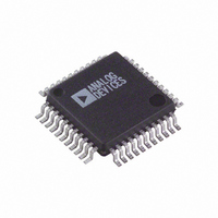
AD1954YS Analog Devices Inc, AD1954YS Datasheet - Page 13

AD1954YS
Manufacturer Part Number
AD1954YS
Description
IC DSP DAC AUDIO3CH/26BIT 44MQFP
Manufacturer
Analog Devices Inc
Series
SigmaDSP®r
Datasheet
1.AD1954YSTZRL.pdf
(36 pages)
Specifications of AD1954YS
Rohs Status
RoHS non-compliant
Number Of Bits
26
Data Interface
Serial
Number Of Converters
3
Voltage Supply Source
Analog and Digital
Power Dissipation (max)
510mW
Operating Temperature
-40°C ~ 105°C
Mounting Type
Surface Mount
Package / Case
44-MQFP, 44-PQFP
Settling Time
-
Available stocks
Company
Part Number
Manufacturer
Quantity
Price
Company:
Part Number:
AD1954YSTZ
Manufacturer:
ADI
Quantity:
624
Company:
Part Number:
AD1954YSTZ
Manufacturer:
Analog Devices Inc
Quantity:
10 000
Part Number:
AD1954YSTZ
Manufacturer:
ADI/亚德诺
Quantity:
20 000
Company:
Part Number:
AD1954YSTZRL
Manufacturer:
Analog Devices Inc
Quantity:
10 000
0 dB and 1/0.75 (approximately 3 dB) will produce larger analog
outputs and result in slightly degraded analog performance. This
extra analog range is necessary in order to pass 0 dBFS square
waves through the system, since these square waves cause over-
shoots in the interpolation filters, which would otherwise briefly
clip the digital DAC circuitry.
A separate digital clipper circuit is used in the DSP core to ensure
that any accumulator values that exceed the numeric 3.23 format
range are clipped when taken from the accumulator.
High-Pass Filter
The high-pass filter is a first order double-precision design.The pur-
pose of the high-pass filter is to remove digital dc from the input. If
this dc were allowed to pass, the detectors used in the compressor/
limiter would give an incorrect reading for low signal levels. The
high-pass filter is controlled by a single parameter (alpha_HPF),
which is programmed by writing to SPI location 180 in 2.20 twos
complement format.The following equation can be used to calcu-
late the parameter alpha_HPF from the –3 dB point of the filter:
REV. A
Alpha_HPF
DATA IN
=
1.0
SERIAL PORT
– EXP
2-BIT SIGN EXTENTION
1.23
–2.0
Figure 4. Numeric Precision and Clipping Structure
3.23
×
p
SIGNAL PROCESSING
×
f
HPF_Cutoff
S
(3.23 FORMAT)
Figure 3. Graphical User Interface
0.75
–13–
FILTERS (3.23 FORMAT)
DAC INTERPOLATION
where EXP is the exponential operator,
pass cutoff in Hz, and f
value for the –3 dB cutoff of the high-pass filter is 2.75 Hz at a
sampling rate of 44.1 kHz.
Biquad Filters
Each of the two input channels has seven second order biquad
sections in the signal path. In addition, the left and right channels
have two additional biquad filters that may be used either as
crossover filters or as additional equalization filters. The subchan-
nel has three additional biquad filters that are also to be used
as equalization and/or crossover filters. In a typical scenario, the
first seven biquads would be used for speaker equalization and/or
tone controls, and the remaining filters would be programmed to
function as crossover filters. Note that there is a common equal-
ization section used for both the main and sub channels, followed
by the crossover filters. This arrangement prevents any interaction
from occurring between the crossover filters and the equalization
filters. One section of the biquad IIR filter is shown in Figure 5.
EXP is the exponential operator,
EXP
CLIPPER
DIGITAL
f
f is the audio sampling rate. The default
S
S
S
S
is the audio sampling rate. The default
DIGITAL -
MODULATORS
(1.23 FORMAT)
HPF_cutoff is the high-
HPF_cutoff is the high-
HPF_cutoff
AD1954


