ADSP-21062KS-133 Analog Devices Inc, ADSP-21062KS-133 Datasheet - Page 36
ADSP-21062KS-133
Manufacturer Part Number
ADSP-21062KS-133
Description
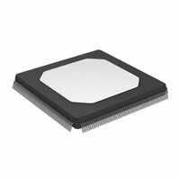
IC DSP CONTROLLER 32BIT 240MQFP
Manufacturer
Analog Devices Inc
Series
SHARC®r
Type
Floating Pointr
Specifications of ADSP-21062KS-133
Rohs Status
RoHS non-compliant
Interface
Host Interface, Link Port, Serial Port
Clock Rate
33MHz
Non-volatile Memory
External
On-chip Ram
256kB
Voltage - I/o
5.00V
Voltage - Core
5.00V
Operating Temperature
0°C ~ 85°C
Mounting Type
Surface Mount
Package / Case
240-MQFP, 240-PQFP
Frequency
33MHz
Supply Voltage
5V
Embedded Interface Type
HPI, Serial
No. Of Mips
40
Supply Voltage Range
4.75V To 5.25V
Operating Temperature Range
0°C To +85°C
Device Core Size
32b
Architecture
Super Harvard
Format
Floating Point
Clock Freq (max)
33MHz
Mips
33
Device Input Clock Speed
33MHz
Ram Size
256KB
Program Memory Size
Not RequiredKB
Operating Supply Voltage (typ)
5V
Operating Supply Voltage (min)
4.75V
Operating Supply Voltage (max)
5.25V
Operating Temp Range
0C to 85C
Operating Temperature Classification
Commercial
Mounting
Surface Mount
Pin Count
240
Package Type
MQFP
Lead Free Status / Rohs Status
Not Compliant
Available stocks
Company
Part Number
Manufacturer
Quantity
Price
Company:

Part Number:
ADSP-21062KS-133
Manufacturer:
Analog Devices Inc
Quantity:
10 000


ADSP-21060/ADSP-21060L/ADSP-21062/ADSP-21062L/ADSP-21060C/ADSP-21060LC
DMA Handshake
These specifications describe the three DMA handshake modes.
In all three modes, DMARx is used to initiate transfers. For
Handshake mode, DMAGx controls the latching or enabling of
data externally. For External handshake mode, the data transfer
is controlled by the ADDR31–0, RD, WR, PAGE, MS3–0, ACK,
Table 22. DMA Handshake
1
2
3
4
5
6
Parameter
Timing Requirements
t
t
t
t
t
t
t
t
Switching Characteristics
t
t
t
t
t
t
t
t
t
t
t
t
t
t
t
W = (number of wait states specified in WAIT register)
HI = t
Only required for recognition in the current cycle.
t
t
See
For ADSP-21062/ADSP-21062L specification is –2.5 ns min, 2 ns max.
For ADSP-21060L/ADSP-21062L specification is –1 ns min.
SDRLC
SDRHC
WDR
SDATDGL
HDATIDG
DATDRH
DMARLL
DMARH
DDGL
WDGH
WDGL
HDGC
VDATDGH
DATRDGH
DGWRL
DGWRH
DGWRR
DGRDL
DRDGH
DGRDR
DGWR
DADGH
DDGHA
SDATDGL
VDATDGH
be driven t
the number of extra cycles that the access is prolonged.
Example System Hold Time Calculation on Page 47
CK
is the data setup requirement if DMARx is not being used to hold off completion of a write. Otherwise, if DMARx low holds off completion of the write, the data can
is valid if DMARx is not being used to hold off completion of a read. If DMARx is used to prolong the read, then t
(if data bus idle cycle occurs, as specified in WAIT register; otherwise HI = 0).
DATDRH
after DMARx is brought high.
DMARx Low Setup Before CLKIN
DMARx High Setup Before CLKIN
DMARx Width Low (Nonsynchronous)
Data Setup After DMAGx Low
Data Hold After DMAGx High
Data Valid After DMARx High
DMARx Low Edge to Low Edge
DMARx Width High
DMAGx Low Delay After CLKIN
DMAGx High Width
DMAGx Low Width
DMAGx High Delay After CLKIN
Data Valid Before DMAGx High
Data Disable After DMAGx High
WR Low Before DMAGx Low
DMAGx Low Before WR High
WR High Before DMAGx High
RD Low Before DMAGx Low
RD Low Before DMAGx High
RD High Before DMAGx High
DMAGx High to WR, RD, DMAGx Low
Address/Select Valid to DMAGx High
Address/Select Hold After DMAGx High
2
5
2
2
for calculation of hold times given capacitive and dc loads.
3
4
1
1
Rev. F | Page 36 of 64 | March 2008
6
t
CK
.
and DMAGx signals. For Paced Master mode, the data transfer
is controlled by ADDR31–0, RD, WR, MS3–0, and ACK (not
DMAG). For Paced Master mode, the Memory Read-Bus Mas-
ter, Memory Write-Bus Master, and Synchronous Read/Write-
Bus Master timing specifications for ADDR31–0, RD, WR,
MS3–0, PAGE, DATA63–0, and ACK also apply.
Min
5
5
6
2
23 + 7DT/8
6
9 + DT/4
6 + 3DT/8
12 + 5DT/8
–2 – DT/8
8 + 9DT/16
0
0
10 + 5DT/8 +W
1 + DT/16
0
11 + 9DT/16 + W
0
5 + 3DT/8 + HI
17 + DT
–0.5
VDATDGH
5 V and 3.3 V
= t
CK
– 0.25t
Max
10 + 5DT/8
16 + 7DT/8
15 + DT/4
6 – DT/8
7
2
3 + DT/16
2
3
CCLK
– 8 + (n × t
CK
) where n equals
Unit
ns
ns
ns
ns
ns
ns
ns
ns
ns
ns
ns
ns
ns
ns
ns
ns
ns
ns
ns
ns
ns
ns
ns
Related parts for ADSP-21062KS-133
Image
Part Number
Description
Manufacturer
Datasheet
Request
R

Part Number:
Description:
±1.7g Dual-Axis IMEMS Accelerometer Evaluation Board
Manufacturer:
Analog Devices Inc
Datasheet:

Part Number:
Description:
Inertial Sensor Evaluation System
Manufacturer:
Analog Devices Inc
Datasheet:
Part Number:
Description:
Manufacturer:
Analog Devices Inc
Datasheet:
Part Number:
Description:
Manufacturer:
Analog Devices Inc
Datasheet:
Part Number:
Description:
Manufacturer:
Analog Devices Inc
Datasheet:
Part Number:
Description:
Manufacturer:
Analog Devices Inc
Datasheet:
Part Number:
Description:
Manufacturer:
Analog Devices Inc
Datasheet:
Part Number:
Description:
Manufacturer:
Analog Devices Inc
Datasheet:
Part Number:
Description:
Manufacturer:
Analog Devices Inc
Datasheet:
Part Number:
Description:
Manufacturer:
Analog Devices Inc
Datasheet:
Part Number:
Description:
Manufacturer:
Analog Devices Inc
Datasheet:
Part Number:
Description:
Manufacturer:
Analog Devices Inc
Datasheet:
Part Number:
Description:
Manufacturer:
Analog Devices Inc
Datasheet: