PVZ3A202A01R00 Murata, PVZ3A202A01R00 Datasheet - Page 82
PVZ3A202A01R00
Manufacturer Part Number
PVZ3A202A01R00
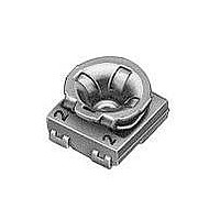
Description
Trimmer Resistors - SMD 2K OHM SMD 3MM
Manufacturer
Murata
Series
PVZ3Ar
Datasheets
1.PVG5A101C01R00.pdf
(89 pages)
2.PVM4A201D01R00.pdf
(55 pages)
3.PVG5A201C01R00.pdf
(90 pages)
Specifications of PVZ3A202A01R00
Resistance
2 KOhms
Tolerance
30 %
Power Rating
0.1 Watt (1/10 Watt)
Operating Temperature Range
- 25 C to + 85 C
Element Type
Carbon
Number Of Turns
1
Product
Single-Turn Trimmer Potentiometers
Taper
Linear
Termination Style
SMD/SMT
Lead Free Status / Rohs Status
Lead free / RoHS Compliant


!Note
• This PDF catalog is downloaded from the website of Murata Manufacturing co., ltd. Therefore, it’s specifications are subject to change or our products in it may be discontinued without advance notice. Please check with our
• This PDF catalog has only typical specifications because there is no space for detailed specifications. Therefore, please approve our product specifications or transact the approval sheet for product specifications before ordering.
sales representatives or product engineers before ordering.
!Note
No.
1
2
3
4
5
Rortary Position Sensors Connector Dust-proof Type (SV21) Specifications and Test Methods
Linearity
Temperature
characteristics
Rotational life
Vibration
Shock
• Please read rating and !CAUTION (for storage, operating, rating, soldering, mounting and handling) in this catalog to prevent smoking and/or burning, etc.
• This catalog has only typical specifications because there is no space for detailed specifications. Therefore, please approve our product specifications or transact the approval sheet for product specifications before ordering.
Item
Linearity is specified the following maximum deviation (C) as percentage of the output voltage (E) from the output voltage
approximate straight-line (Y) in FS (full scale) within the electrical effective rotational angle.
Approximate straight-line (Y=m +b) is calculated by least square from measured output voltage curve.
FS is specified the range from min. output voltage (Y min.) to max. output voltage (Y max.) of approximate straight-line within the
electrical effective rotational angle.
Temperature characteristics is specified as percentage the maximum deviation of output voltage from that at 25 2 C in FS (full
scale).
The adjustment rotor should be continuously rotated within 100 of effective electrical rotational angle, at the rate of one cycle for
1 seconds for 10 Million cycles under the condition of 25 2 C of temperature without loading.
The rotary position sensor should be tested under the condition of the amplitude of 1.5mm, the frequency range from 10 to 55Hz
(should be traversed in approximately one minute) and 2 hours in each of 3 mutually perpendicular directions (total 6 hours).
The rotary position sensor should be tested under the condition of the peak acceleration 100G max. in half-sine wave and 4
shocks in each of 3 mutually perpendicular directions (total 12 shocks).
(Linearity = C/FS x 100%)
Y= Approximate straight-line of output voltage (V)
C= Maximum deviation of output voltage (E1) from output voltage approximate straight-line (Y1)
= Rotational angle ( )
Electrical Effective Rotaitional Angle
Rotaitional Angle
Test Methods
0
Y=mX+b
E
1
(V)
Y
C
1
(V)
Y max.
FS
Y min.
R50E.pdf
81
05.9.9
9
Related parts for PVZ3A202A01R00
Image
Part Number
Description
Manufacturer
Datasheet
Request
R

Part Number:
Description:
Murata Microblower 20x20 DCDC Driver Board - Samples Only
Manufacturer:
Murata
Part Number:
Description:
357-036-542-201 CARDEDGE 36POS DL .156 BLK LOPRO
Manufacturer:
Murata
Datasheet:
Part Number:
Description:
Manufacturer:
Murata
Datasheet:
Part Number:
Description:
Manufacturer:
Murata
Datasheet:
Part Number:
Description:
Manufacturer:
Murata
Datasheet:
Part Number:
Description:
Manufacturer:
Murata
Datasheet:
Part Number:
Description:
Manufacturer:
Murata
Datasheet:
Part Number:
Description:
Manufacturer:
Murata
Datasheet:
Part Number:
Description:
Manufacturer:
Murata
Datasheet:
Part Number:
Description:
BLM21BD751SN1On-Board Type (DC) EMI Suppression Filters
Manufacturer:
Murata
Datasheet:
Part Number:
Description:
BLM15AG100SN1On-Board Type (DC) EMI Suppression Filters
Manufacturer:
Murata
Datasheet:
Part Number:
Description:
NFE31PT222Z1E9On-Board Type (DC) EMI Suppression Filters
Manufacturer:
Murata
Datasheet:
Part Number:
Description:
Chip Coil
Manufacturer:
Murata
Datasheet:
Part Number:
Description:
Chip Coil
Manufacturer:
Murata
Datasheet: