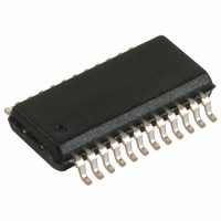
CY7C63101A-QC Cypress Semiconductor Corp, CY7C63101A-QC Datasheet - Page 14

CY7C63101A-QC
Manufacturer Part Number
CY7C63101A-QC
Description
IC MCU 4K LS USB MCU 24-QSOP
Manufacturer
Cypress Semiconductor Corp
Series
M8™r
Datasheet
1.CY7C63101A-QC.pdf
(25 pages)
Specifications of CY7C63101A-QC
Applications
USB Microcontroller
Core Processor
M8A
Program Memory Type
OTP (4 kB)
Controller Series
CY7C631xx
Ram Size
128 x 8
Interface
USB
Number Of I /o
16
Voltage - Supply
4 V ~ 5.25 V
Operating Temperature
0°C ~ 70°C
Mounting Type
Surface Mount
Package / Case
24-QSOP
Lead Free Status / RoHS Status
Contains lead / RoHS non-compliant
Other names
428-1314
Available stocks
Company
Part Number
Manufacturer
Quantity
Price
6.9.2
All USB devices are required to have an endpoint number 0
that is used to initialize and manipulate the device. Endpoint 0
provides access to the device’s configuration information and
allows generic USB status and control accesses.
Endpoint 0 can receive and transmit data. Both receive and
transmit data share the same 8-byte Endpoint 0 FIFO located
at data memory space 0x70 to 0x77. Received data may
overwrite the data previously in the FIFO.
This is a read/write register located at I/O address 0x14. Any
write to this register clears all bits except bit 3 which remains
unchanged. All bits are cleared during reset.
Bit 0 is set to 1 when a SETUP token for Endpoint 0 is received.
Once set to a 1, this bit remains HIGH until it is cleared by an
I/O write or a reset. While the data following a SETUP is being
received by the USB engine, this bit is not cleared by an I/O
write. User firmware writes to the USB FIFOs are disabled
when bit 0 is set. This prevents SETUP data from being
overwritten.
Bits 1 and 2 are updated whenever a valid token is received
on Endpoint 0. Bit 1 is set to 1 if an OUT token is received and
cleared to 0 if any other token is received. Bit 2 is set to 1 if an
IN token is received and cleared to 0 if any other token is
received.
Bit 3 shows the Data Toggle status of DATA packets received
on Endpoint 0. This bit is updated for DATA following SETUP
tokens and for DATA following OUT tokens if Stall (bit 5 of
0x10) is not set and either EnableOuts or StatusOuts (bits 3
and 4 of 0x13) are set.
Bits 4 to 7 are the count of the number of bytes received in a
DATA packet. The two CRC bytes are included in the count,
so the count value is two greater than the number of data bytes
Table 6-4. USB Engine Response to SETUP and OUT Transactions on Endpoint 0
Document #: 38-08026 Rev. *A
COUNT3
Stall
R/W
–
–
0
0
0
0
1
1
0
0
0
b7
0
Control Bit Settings
Endpoint 0
Status Out Enable Out
–
–
0
0
0
0
0
0
1
1
1
COUNT2
R/W
b6
0
–
–
1
1
0
0
0
0
0
0
0
Figure 6-21. USB Endpoint 0 RX Register (Address 0x14)
COUNT1
R/W
b5
0
SETUP
SETUP
Received Packets
Token
Type
OUT
OUT
OUT
OUT
OUT
OUT
OUT
OUT
OUT
COUNT0
N/Status
R/W
Packet
Status
b4
Data
Valid
Error
Valid
Error
Valid
Error
Valid
Error
Error
0
FIFO Write
6.9.2.1 Endpoint 0 Receive
After receiving a packet and placing the data into the Endpoint
0 FIFO, the USB Controller updates the USB Endpoint 0 RX
register to record the receive status and then generates a USB
Endpoint 0 interrupt. The format of the Endpoint 0 RX Register
is shown in Figure 6-21.
received. The count is always updated and the data is always
stored in the FIFO for DATA packets following a SETUP token.
The count for DATA following an OUT token is updated if Stall
(bit 5 of 0x10) is 0 and either EnableOuts or StatusOuts (bits
3 and 4 of 0x13) are 1. The DATA following an OUT is written
into the FIFO if EnableOuts is set to 1 and Stall and StatusOuts
are 0.
A maximum of eight bytes are written into the Endpoint 0 FIFO.
If there are less than eight bytes of data the CRC is written into
the FIFO.
Due to register space limitations, the Receive Data Invalid bit
is located in the USB Endpoint 0 TX Configuration Register.
Refer to the Endpoint 0 Transmit section for details. This bit is
set by the SIE if an error is detected in a received DATA packet.
Table 6-4 summarizes the USB Engine response to SETUP
and OUT transactions on Endpoint 0. In the Data Packet
column ‘Error’ represents a packet with a CRC, PID or bit-
stuffing error, or a packet with more than eight bytes of data.
‘Valid’ is a packet without an Error. ‘Status’ is a packet that is
a valid control read Status stage, while ‘N/Status’ is not a
correct Status stage (see section 6.9.4). The ‘Stall’ bit is
described
‘EnableOuts’ bits are described in section 6.9.4.
TOGGLE
Yes
Yes
Yes
Yes
No
No
No
No
No
No
No
b3
R
0
in
Update
Toggle
Yes
Yes
Yes
Yes
Yes
Yes
Yes
No
No
No
No
Section
USB Engine Response
R/W
b2
IN
0
Update
Count
6.9.2.2.
Yes
Yes
Yes
Yes
Yes
Yes
No
No
No
No
No
OUT
R/W
b1
The
0
Interrupt
CY7C63001A
CY7C63101A
Yes
Yes
Yes
Yes
Yes
Yes
No
No
No
No
No
‘StatusOuts’
Page 14 of 25
SETUP
R/W
STALL
STALL
Reply
b0
None
None
None
None
None
0
ACK
ACK
NAK
ACK
and


