GLC65B SL Power, GLC65B Datasheet - Page 2
GLC65B
Manufacturer Part Number
GLC65B
Description
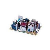
Linear & Switching Power Supplies 65W +5.1/+15/-15V
Manufacturer
SL Power
Series
GLCr
Datasheet
1.GLC65EG.pdf
(2 pages)
Specifications of GLC65B
Product
Switching
Commercial/medical
Commercial
Output Power Rating
36 W
Input Voltage
90 VAC to 264 VAC
Number Of Outputs
3
Output Voltage (channel 1)
5.1 V
Output Current (channel 1)
7 A
Output Voltage (channel 2)
15 V
Output Current (channel 2)
2.5 A
Output Voltage (channel 3)
- 15 V
Output Current (channel 3)
2 A
Mounting Style
Chassis
Dimensions
127 mm L x 76.2 mm W
Open Frame/enclosed
Open Frame
Output Type
Triple Output
Lead Free Status / Rohs Status
Lead free / RoHS Compliant


Notes:
A. Continuous individual output ratings for unrestricted convection cooling. Combination of individual output loads must not exceed total power rating.
B. Peak rating for 60 s 10% duty cycle or continuous rating 150 LFM forced air cooling.
C. Adjustment on V1 varies all outputs simultaneously (1% on V1 @ 1% on V2 & V3).
D. Total combined current of V1 & V2 not to exceed 12 A. Combination of individual output loads must not exceed total power rating.
E. Total regulation is defined as maximum deviation from the initial set point. With all other outputs at 50% load, output under test can be varied from 0 to 100% load
and varied to any ac line voltage. Initial set point is 1% on V1, 2% on V2 and 3% on V3
F. Add “G” suffix to model number for RoHS compliant model.
SL Power Electronics Corp., 6050 King Drive, Bldg. A, Ventura, CA 93003, USA. Phone:(805) 486 4565 Fax:(805) 487 8911 www.slpower.com Rev. 09/10/08. Data Sheet ©
2008 SL Power Electronics Corp. The information and specifications contained in this data sheet are believed to be correct at time of publication.
However, SL Power accepts no responsibility for consequences arising from reproduction errors or inaccuracies. Specifications are subject to change without notice.
GLC65 MECHANICAL SPECIFICATIONS
Commercial
Model
GLC65A
GLC65B
GLC65D
GLC65E
GLC65G
GLC65H
ENVIRONMENTAL SPECIFICATIONS
Temperature (A)
Humidity (A)
Shock (B)
Altitude
Vibration (C)
Medical
Model
GLM65A
GLM65B
GLM65D
GLM65E
GLM65G
GLM65H
Output No.
1
2
3
1
2
3
1
2
3
1
2
3
1
2
3
1
2
3
OPERATING
0 TO 50°C
0 to 95% RH
20 g
-500 to 10,000 ft
1.5 g
pk
rms’
0.003 g
Output
+5.0 V
+5.1 V
+5.0 V
+5.0 V
+5.0 V
+3.3 V
+3.3 V
+5.0 V
+12 V
+15 V
+24 V
+24 V
+12 V
+12 V
+12 V
-12 V
-15 V
-12 V
2
/Hz
NON-OPERATING
-40 to +85°C
0 to 95% RH
40 g
-500 to 40,000 ft
5 g
Maximum (A)
rms’
pk
Output
0.026 g
2.5 A
2.5 A
1.5 A
2.5 A
1.5 A
2.5 A
2.5 A
2.5 A
3 A
7 A
2 A
7 A
7 A
5 A
4 A
5 A
4 A
7 A
2
/Hz
Maximum (B)
Output
A. Units should be allowed to warm up/operate under non-condensing con-
ditions before application of power. Derate output current and total output
power by 2.5% per °C above 50°C. For operation in a confined space, moving
air may be required. Under all conditions, the cooling vs. load profile should
be such that heat sinks and/or heatsink temperatures do not exceed 90 °C
for extended periods.
B. Shock testing—half-sinusoidal, 10 ± 3 ms duration, ± direction, 3 orthogo-
nal axes, total 6 shocks.
C. Random vibration—10 to 2000Hz, 6dB/octave roll-off from 350 to 2000Hz,
3 orthogonal axes. Tested for 10 min./axis operating and 1 hr./axis non-op-
erating.
2.5 A
2.5 A
5 A
4 A
9 A
4 A
3 A
9 A
4 A
9 A
4 A
8 A
5 A
4 A
8 A
6 A
3 A
9A
Regulation (E)
Total
3.5%
4.5%
2%
5%
6%
2%
4%
5%
2%
3%
6%
2%
3%
6%
3%
3%
6%
6%
1.20
30.28
V1 Adjustment
Note (C)
± 5%
± 5%
± 5%
± 5%
± 5%
± 5%
—
—
—
—
—
—
—
—
—
—
—
—
6.2 ± 0.6 V
6.2 ± 0.6 V
6.2 ± 0.6 V
6.2 ± 0.6 V
6.2 ± 0.6 V
4.3 ± 0.8 V
OVP Set-
point
—
—
—
—
—
—
—
—
—
—
—
—
Ripple/
Noise
1%
1%
1%
1%
1%
1%
1%
1%
1%
1%
1%
1%
1%
1%
1%
1%
1%
1%
Related parts for GLC65B
Image
Part Number
Description
Manufacturer
Datasheet
Request
R

Part Number:
Description:
POWER SUPPLY, SWITCHING; 65 W; 90 TO 264 VAC; 12 V; 1.7 A (MAX.); 5.5 A; 2%; 2%
Manufacturer:
SL Power ( Ault / Condor )
Datasheet:
Part Number:
Description:
POWER SUPPLY, SWITCHING; 65 W; 90 TO 264 VAC; 15 V; 1.7 A (MAX.); 4.3 A; 2%; 2%
Manufacturer:
SL Power ( Ault / Condor )
Datasheet:
Part Number:
Description:
POWER SUPPLY, SWITCHING; 65 W; 90 TO 264 VAC; 24 V; 1.7 A (MAX.); 2.7 A; 2%; 2%
Manufacturer:
SL Power ( Ault / Condor )
Datasheet:
Part Number:
Description:
POWER SUPPLY, SWITCHING; 65 W; 90 TO 264 VAC; 5.1 V; 1.7 A (MAX.); 11 A; 2%; 2%
Manufacturer:
SL Power ( Ault / Condor )
Datasheet:
Part Number:
Description:
POWER SUPPLY, SWITCHING; 65 W; 90 TO 264 VAC; 28 V; 1.7 A (MAX.); 2.3 A; 2%; 2%
Manufacturer:
SL Power ( Ault / Condor )
Datasheet:

Part Number:
Description:
PWR SPLY SWITCHER 65W 48V
Manufacturer:
SL Power Electronics Manufacture of Condor/Ault Brands
Datasheet:
Part Number:
Description:
Glc65 Commercial/glm65 Medical 65 Watt Multiple Output Global Performance Switchers
Manufacturer:
SL Power Electronics
Datasheet:

Part Number:
Description:
Linear & Switching Power Supplies 65W 28V @ 2.3A
Manufacturer:
SL Power
Datasheet:
Part Number:
Description:
Linear & Switching Power Supplies 65W 5.1V @ 11A
Manufacturer:
SL Power
Datasheet:

Part Number:
Description:
LEAD, IEC C19 TO EURO PLUG, 1M
Manufacturer:
MULTICOMP
Datasheet:

Part Number:
Description:
50W, 36-75Vin, Single, 2.5V@20A, 1/16 Brick Open Frame, 89% Eff, Pos, SMT, RoHS 6
Manufacturer:
Emerson Network Power
Datasheet:
Part Number:
Description:
System Power Supplies
Manufacturer:
SL Power Electronics
Datasheet:
Part Number:
Description:
Switching Power Supply Modules
Manufacturer:
SL Power Electronics
Datasheet:
Part Number:
Description:
Cent1120 Universal 120 Watt Series
Manufacturer:
SL Power Electronics
Datasheet:
Part Number:
Description:
Gpfc110 Commercial 110 Watt Global Performance Switchers
Manufacturer:
SL Power Electronics
Datasheet: