DP83848KSQ/NOPB National Semiconductor, DP83848KSQ/NOPB Datasheet - Page 35
DP83848KSQ/NOPB
Manufacturer Part Number
DP83848KSQ/NOPB
Description
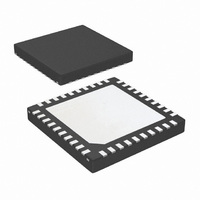
IC TXRX ETHERNET PHYTER 40-LLP
Manufacturer
National Semiconductor
Type
Transceiverr
Datasheet
1.DP83848KSQNOPB.pdf
(78 pages)
Specifications of DP83848KSQ/NOPB
Number Of Drivers/receivers
1/1
Protocol
Ethernet
Voltage - Supply
3 V ~ 3.6 V
Mounting Type
Surface Mount
Package / Case
40-LLP
For Use With
DP83848K-MAU-EK - BOARD EVALUATION DP83848K
Lead Free Status / RoHS Status
Lead free / RoHS Compliant
Other names
DP83848KSQ
DP83848KSQTR
DP83848KSQTR
Available stocks
Company
Part Number
Manufacturer
Quantity
Price
Company:

Part Number:
DP83848KSQ/NOPB
Manufacturer:
TI
Quantity:
3 400
Part Number:
DP83848KSQ/NOPB
Manufacturer:
TI/德州仪器
Quantity:
20 000


5.4 POWER FEEDBACK CIRCUIT
To ensure correct operation for the DP83848K, parallel
caps with values of 10 F (Tantalum) and 0.1 F should be
placed close to pin 19 (PFBOUT) of the device.
Pin 16 (PFBIN1) and pin 30 (PFBIN2) must be connected
to pin 19 (PFBOUT), each pin requires a small capacitor
(0.1 F). See Figure 13 below for proper connections.
5.5 POWER DOWN
The device can be put in a Power Down mode by setting bit
11 (Power Down) in the Basic Mode Control Register,
BMCR (0x00h).
Pin 19 (PFBOUT)
Pin 30 (PFBIN2)
Pin 16 (PFBIN1)
Figure 13. Power Feedback Connection
0.1 F
0.1 F
10 F
+
-
0.1 F
35
5.6 ENERGY DETECT MODE
When Energy Detect is enabled and there is no activity on
the cable, the DP83848K will remain in a low power mode
while monitoring the transmission line. Activity on the line
will cause the DP83848K to go through a normal power up
sequence. Regardless of cable activity, the DP83848K will
occasionally wake up the transmitter to put ED pulses on
the line, but will otherwise draw as little power as possible.
Energy detect functionality is controlled via register Energy
Detect Control (EDCR), address 0x1Dh.
6.0 Reset Operation
The DP83848K includes an internal power-on reset (POR)
function and does not need to be explicitly reset for normal
operation after power up. If required during normal opera-
tion, the device can be reset by a hardware or software
reset.
6.1 HARDWARE RESET
A hardware reset is accomplished by applying a low pulse
(TTL level), with a duration of at least 1
RESET_N. This will reset the device such that all registers
will be reinitialized to default values and the hardware con-
figuration values will be re-latched into the device (similar
to the power-up/reset operation).
6.2 SOFTWARE RESET
A software reset is accomplished by setting the reset bit
(bit 15) of the Basic Mode Control Register (BMCR). The
period from the point in time when the reset bit is set to the
point in time when software reset has concluded is approx-
imately 1 s.
The software reset will reset the device such that all regis-
ters will be reset to default values and the hardware config-
www.national.com
s, to the
Related parts for DP83848KSQ/NOPB
Image
Part Number
Description
Manufacturer
Datasheet
Request
R

Part Number:
Description:
BOARD EVALUATION DP83848K
Manufacturer:
National Semiconductor
Datasheet:
Part Number:
Description:
National Semiconductor [8-Bit D/A Converter]
Manufacturer:
National Semiconductor
Datasheet:
Part Number:
Description:
National Semiconductor [Media Coprocessor]
Manufacturer:
National Semiconductor
Datasheet:
Part Number:
Description:
Digitally Controlled Tone and Volume Circuit with Stereo Audio Power Amplifier, Microphone Preamp Stage and National 3D Sound
Manufacturer:
National Semiconductor
Datasheet:
Part Number:
Description:
Digitally Controlled Tone and Volume Circuit with Stereo Audio Power Amplifier, Microphone Preamp Stage and National 3D Sound
Manufacturer:
National Semiconductor
Datasheet:
Part Number:
Description:
AC97 Rev 2 Codec with Sample Rate Conversion and National 3D Sound
Manufacturer:
National Semiconductor
Part Number:
Description:
Manufacturer:
National Semiconductor
Datasheet:
Part Number:
Description:
Manufacturer:
National Semiconductor
Datasheet:
Part Number:
Description:
General Purpose, Low Voltage, Low Power, Rail-to-Rail Output Operational Amplifiers
Manufacturer:
National Semiconductor
Datasheet:
Part Number:
Description:
8-bit 20 MSPS flash A/D converter.
Manufacturer:
National Semiconductor
Datasheet:
Part Number:
Description:
Low Noise Quad Operational Amplifier
Manufacturer:
National Semiconductor
Datasheet:
Part Number:
Description:
Quad Differential Line Receivers
Manufacturer:
National Semiconductor
Datasheet:
Part Number:
Description:
Quad High Speed Trapezoidal? Bus Transceiver
Manufacturer:
National Semiconductor
Datasheet:
Part Number:
Description:
Dual Line Receiver
Manufacturer:
National Semiconductor
Datasheet: