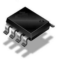
U643B-MFPY Atmel, U643B-MFPY Datasheet - Page 6

U643B-MFPY
Manufacturer Part Number
U643B-MFPY
Description
Motor / Motion / Ignition Controllers & Drivers Flash Control
Manufacturer
Atmel
Type
Flasher ICr
Datasheet
1.U643B-MFPG3Y.pdf
(9 pages)
Specifications of U643B-MFPY
Mounting Style
SMD/SMT
Package / Case
SOIC
Lead Free Status / Rohs Status
Lead free / RoHS Compliant
Available stocks
Company
Part Number
Manufacturer
Quantity
Price
Part Number:
U643B-MFPY
Manufacturer:
TFK
Quantity:
20 000
5. Absolute Maximum Ratings
Stresses beyond those listed under “Absolute Maximum Ratings” may cause permanent damage to the device. This is a stress rating
only and functional operation of the device at these or any other conditions beyond those indicated in the operational sections of this
specification is not implied. Exposure to absolute maximum rating conditions for extended periods may affect device reliability.
Reference point pin 1
6. Thermal Resistance
7. Electrical Characteristics
Typical values under normal operation in application circuit (see
Reference point ground (–31), T
6
Parameters
Supply voltage
Surge Forward Current
t
t
t
Output current
Power Dissipation
T
T
Junction temperature
Ambient temperature range
Storage temperature range
Parameters
Junction ambient
Parameters
Supply voltage range
Supply current
Relay output:
Saturation voltage
Reverse current
Start delay
Frequency tolerance
Bright period
Frequency increase
Control signal threshold
Leakage resistance
Lamp load
P
P
P
amb
amb
= 300 ms
= 0.1 ms
= 300 ms
= 95°C
= 60°C
U643B
amb
Pins 2 and 6
Pins 2 and 6
Pins 2 and 6
Pin 8
Pin 3
DIP 8
SO8
DIP 8
SO8
DIP8
SO8
= 25°C, unless otherwise specified.
Test Conditions
Pins 2 and 6
Pins 2 and 6
Dark phase
Bright phase
Pin 3
I
with resistance = 60
First bright phase
Basic frequency f
Control frequency f
Lamp outage
V
V
V
49a to GND
O
S
S
S
= 150 mA, V
= 9V, pin 7
= 12V, pin 7
= 15V, pin 7
S
Symbol
Symbol
= 9V
1
R
R
T
I
I
I
T
P
P
P
P
V
FSM
FSM
FSM
2
T
I
amb
thJA
thJA
stg
O
tot
tot
tot
tot
S
J
Figure 2-1 on page
Symbol
V
S
2), V
V
V
V
V
R
(+49)
t
P
I
I
I
f
on
S
S
O
f
R3
R3
R3
2
f
f
O
1
P
L
–55 to +150
1
2
–40 to +95
S
Value
Value
(+49, pin 2 and 6) = 12V.
16.5
420
340
690
560
150
110
160
1.5
1.0
0.3
50
2.15 f
Min.
–5
47
37
85
66
76
1
1
9 to 15
Typ.
4.5
7.0
91
71
81
4
2.3 f
Max.
1.0
0.1
11
10
+5
53
45
97
76
87
8
5
4727B–AUTO–09/05
1
Unit
Unit
K/W
K/W
mW
mW
mW
mW
mA
°C
°C
°C
V
A
A
A
Unit
mA
mA
mA
mV
mV
mV
ms
Hz
k
%
%
%
W
V
V


