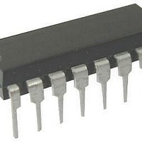
L482/1 STMicroelectronics, L482/1 Datasheet

L482/1
Specifications of L482/1
Related parts for L482/1
L482/1 Summary of contents
Page 1
HALL–EFFECT PICKUP IGNITION CONTROLLER . DIRECT DRIVING OF . POWER DARLINGTON COIL CURRENT CHARGING ANGLE (DWELL) . CONTROL . COIL CURRENT PEAK VALUE LIMITATION . CONTINUOUS COIL CURRENT PROTECTION CONDUCTION AND DESATURATION TIME . OUTPUT SIGNALS PERMANENT CONDUCTION PROTECTION ...
Page 2
L482 ABSOLUTE MAXIMUM RATINGS Symbol V Reverse Battery Voltage R V Dump Voltage D P Power Dissipation at T tot Junction and Storage Temperature Range j stg BLOCK DIAGRAM THERMAL DATA Symbol R Thermal Resistance Junction-ambient (DIP16) ...
Page 3
PIN FUNCTIONS (refer to fig. 3 for DIP16 package) N Name 1 CONDUCTION TIME SIGNAL 2 HALL-EFFECT INPUT 3 DWELL CONTROL 4 DWELL CONTROL TIMER 5 HALL SENSOR SUPPLY 6 DESATURATION TIME SIGNAL 7 REFERENCE VOLTAGE 8 PERMANENT CONDUCT. PROTECTION ...
Page 4
L482 PIN FUNCTIONS (continued) N Name 13 GROUND 14 DRIVER COLLECTOR 15 OVERVOLTAGE LIMITATION 16 DRIVING STAGE OUTPUT (*) These pins refer only to the DIP package type. For the SO 16 version the permanent conduction reset output signal is ...
Page 5
ELECTRICAL CHARACTERISTICS (Continued) Symbol Parameter t Permanent PC Protection Time (pin 8) (see fig Charging Angle Output Voltage 1 LOW HIGH V Desat. Time Output 6 Voltage I Desat. Time Leakage Current 6L (pin6) I Permanent Conduction Reset ...
Page 6
L482 Figure 2 : Low Frequency Condition and Permanent Conduction Protection. Figure 3 : Application circuit (DIP–16). 6/11 ...
Page 7
Figure 4 : Application Circuit (SO–16). CIRCUIT OPERATION The L482 control the conduction time (dwell) and the peak value of the primary current in the coil over the full range of operating conditions. The coil current is limited to a ...
Page 8
L482 DESATURATION TIMES IN LOW AND HIGH FRE- QUENCY OPERATION. Due to the upper limit of the voltage range of pin 3, if the components of fig are used, below 10Hz (300RPM for a 4 cylinder en- gine) ...
Page 9
DIM. MIN. TYP. MAX. MIN. a1 0.51 0.020 B 0.77 1.65 0.030 b 0 8.5 e 2.54 e3 17.78 F 7.1 I 5.1 L 3.3 Z 1.27 inch MECHANICAL DATA TYP. MAX. 0.065 0.020 ...
Page 10
L482 mm DIM. MIN. TYP. MAX. MIN. A 1.75 a1 0.1 0.25 0.004 a2 1.6 b 0.35 0.46 0.014 b1 0.19 0.25 0.007 C 0.5 c1 45˚ (typ.) D (1) 9.8 10 0.386 E 5.8 6.2 0.228 e 1.27 e3 ...
Page 11
... No license is granted by implication or otherwise under any patent or patent rights of STMicroelectronics. Specification mentioned in this publication are subject to change without notice. This publication supersedes and replaces all information previously supplied. STMi- croelectronics products are not authorized for use as critical components in life support devices or systems without express written approval of STMicroelectronics ...


