EL1508CL Intersil, EL1508CL Datasheet - Page 14
EL1508CL
Manufacturer Part Number
EL1508CL
Description
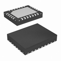
IC LINE DRIVER ADSL 24-QFN
Manufacturer
Intersil
Type
Driverr
Datasheet
1.EL1508CL.pdf
(18 pages)
Specifications of EL1508CL
Number Of Drivers/receivers
1/0
Voltage - Supply
5 V ~ 12 V
Mounting Type
Surface Mount
Package / Case
24-VQFN Exposed Pad, 24-HVQFN, 24-SQFN, 24-DHVQFN
Lead Free Status / RoHS Status
Contains lead / RoHS non-compliant
Protocol
-
Available stocks
Company
Part Number
Manufacturer
Quantity
Price
Company:

Part Number:
EL1508CL
Manufacturer:
ELANTEC
Quantity:
18 888
Company:
Part Number:
EL1508CL
Manufacturer:
Elantec
Quantity:
289
Company:
Part Number:
EL1508CL-AAA
Manufacturer:
EL
Quantity:
336
Part Number:
EL1508CLZ
Manufacturer:
INTERSIL
Quantity:
20 000


Pd
combination of the quiescent power and the output stage
power when driving the line:
Pd
In the full power mode and with 6.8k R
EL1508 consumes typically 7mA quiescent current and still
able to maintain very low distortion. The distortion results are
shown in typical performance section of the data sheet.
When driving a load, a large portion (about 50%) of the
quiescent current becomes output load current:
where:
The θ
using the equation:
where:
Pd
Θ
Θ
JA
FIGURE 44. TYPICAL ADSL CO LINE DRIVER
Pd = 598mW
T
T
P
θ
package when mounted on the PCB
JA
=
AMB
JA
=
JUNCT
=
DISS
FROM
=
=
P
AFE
V
JA
12
is the junction to ambient thermal resistance for the
quiescent
S
T
--------------------------------------------
150 85
--------------------- -
598mW
JUNCT
is the maximum ambient temperature (85°C)
×
requirement needs to be calculated. This is done
×
is the dissipation calculated above
T
1.5kΩ
T
I
(
X
is the maximum die temperature (150°C)
Q
7mA
2R
X
–
+
P
-
+
DISS
G
IMPLEMENTATION
(
V
–
+
×
=
S
T
P
50% )
AMB
108°C/W
–
+
+
R
-
-
output-stage
R
3k
3k
2
F
F
V
V
V
V
×
S
S
S
S
V
+
+
+
-
-
OUT-RMS
(
12V
R
R
10
10
14
T
T
–
0.22µF
3.16 )
0.22µF
)
×
I
×
OUT-RMS
ADJ
31.6mA
TXFR 1:1
registers, the
×
2
100
EL1508
PCB Layout Considerations for QFN and SOIC
Packages
The EL1508 die is packaged in three different thermally-
efficient packages: a 20 Ld SOIC (0.300”), a 16 Ld SOIC
(0.150”), and a 24 Ld QFN. The 16 Ld SOIC has the same
external dimensions as a standard 0.150” width SOIC
package, but has the center four leads (two per side)
internally-fused for heat transfer purposes. Both packages
can use PCB surface metal vias areas and internal ground
planes, to spread heat away from the package. The larger
the PCB area the lower the junction temperature of the
device will be. In XDSL applications, multiple layer circuit
boards with internal ground plane are generally used. 13 mil
vias are recommended to connect the metal area under the
device with the internal ground plane. Examples of the PCB
layouts are shown in the figures below that result in thermal
resistance θ
for the SOIC package. The thermal resistance is obtained
with the EL1508CL and CS demo boards. The demo board
is a 4-layer board built with 2oz. copper and has a dimension
of 4in
guideline to achieve these results. In addition to lower
thermal resistance, the QFN package exhibits much lower
2nd harmonic distortion.
A separate Application Note for the QFN package and layout
recommendations is also available.
2
. Note, the user must follow the thermal layout
INTERNAL GROUND PLANE (24 LD QFN)
JA
of 37°C/W for the QFN package and 47°C/W
TOP (24 LD QFN)
March 26, 2007
FN7014.5
Related parts for EL1508CL
Image
Part Number
Description
Manufacturer
Datasheet
Request
R

Part Number:
Description:
Differential DSL Line Driver
Manufacturer:
Intersil
Datasheet:

Part Number:
Description:
Intersil Corporation [CMOS Serial Controller Interface]
Manufacturer:
Intersil Corporation
Datasheet:
Part Number:
Description:
Manufacturer:
Intersil Corporation
Datasheet:
Part Number:
Description:
357-036-542-201 CARDEDGE 36POS DL .156 BLK LOPRO
Manufacturer:
Intersil Corporation
Datasheet:
Part Number:
Description:
1024-Word x 4-Bit LSI Static RAM
Manufacturer:
Intersil Corporation
Datasheet:
Part Number:
Description:
General Purpose NPN Transistor Arrays FN341.4
Manufacturer:
Intersil Corporation
Datasheet:
Part Number:
Description:
CMOS 16-Bit Microprocessor
Manufacturer:
Intersil Corporation
Datasheet:
Part Number:
Description:
Manufacturer:
Intersil Corporation
Datasheet:
Part Number:
Description:
Manufacturer:
Intersil Corporation
Datasheet:
Part Number:
Description:
Manufacturer:
Intersil Corporation
Datasheet:
Part Number:
Description:
Manufacturer:
Intersil Corporation
Datasheet:
Part Number:
Description:
CMOS 6-Bit Latch and Decoder Memory Interfaces
Manufacturer:
Intersil Corporation
Datasheet:
Part Number:
Description:
CA3046General Purpose NPN Transistor Arrays
Manufacturer:
Intersil Corporation
Datasheet:
Part Number:
Description:
Manufacturer:
Intersil Corporation
Datasheet:
Part Number:
Description:
TR909 DLC/FLC SLIC with Low Power Standby
Manufacturer:
Intersil Corporation
Datasheet: