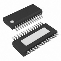
MAX9526AEI+ Maxim Integrated Products, MAX9526AEI+ Datasheet - Page 27

MAX9526AEI+
Manufacturer Part Number
MAX9526AEI+
Description
IC VID DECODER NTSC/PAL 28-QSOP
Manufacturer
Maxim Integrated Products
Type
Video Decoderr
Datasheet
1.MAX9526AEI.pdf
(38 pages)
Specifications of MAX9526AEI+
Applications
Automotive Systems, Players, TV
Voltage - Supply, Analog
1.8V
Voltage - Supply, Digital
1.8V
Mounting Type
Surface Mount
Package / Case
28-QSOP
Operating Supply Voltage
1.8 V
Maximum Operating Temperature
+ 125 C
Bandwidth
180 Hz to 2 KHz
Maximum Power Dissipation
1009 mW
Minimum Operating Temperature
- 40 C
Mounting Style
SMD/SMT
Snr
58.8 dB
Lead Free Status / RoHS Status
Lead free / RoHS Compliant
1 = Automatically selects video input with activity
When activity is present on both or neither V
V
shutdown), V
and no activity on V
V
activity, the input switches to V
goes away on V
0 = Video input is selected manually (default).
See INSEL (register 0x09, B6) for manual input selection.
1 = Select V
0 = Select V
Video autoselect bit (AUTOSEL) must be 0 for this reg-
ister to take effect.
1 = Chroma gain is frozen.
0 = Automatic chroma gain is based on color burst
To freeze the chroma gain at the default value of 17
(hex), set CRAGC = 1 and apply a soft reset.
1 = Digital composite gain frozen at default value
Video Input Select and Clamp Control Register
Gain-Control Register
IN2
IN2
level ( default).
(80 (hex)).
0x0A
REG
0x09
REG
detect.
after a reset (POR, register reset, sleep mode,
is automatically selected with the presence of
IN2
IN1
IN1
.
AUTOSEL
(default).
IN2
CRAGC
Chrominance AGC Disable (CRAGC)
is selected. If there is activity on V
Composite AGC Disable (CMPAGC)
______________________________________________________________________________________
B7
B7
.
Manual Video Input Select (INSEL)
IN1
Video Auto-Select (AUTOSEL)
, then V
CMPAGC
INSEL
B6
B6
IN2
IN1
is selected. When
only when activity
DCRESTORE_RANGE
Low-Power, High-Performance
B5
B5
0
IN1
and
IN2
NTSC/PAL Video Decoder
ADAGC
B4
B4
This bit sets the full-scale range of the DC restoration
DAC. Increasing the full-scale current range increases
the bandwidth and range of the DC restoration loop.
10 = Slow (±3µA into video input coupling capacitor)
11 = Medium (±6µA into video input coupling capacitor)
00 = Medium-fast (±12µA into video input coupling
01 = Fast (±24µA into video input coupling capacitor)
This bit disables the digital clamp.
1 = Disables digital sync-tip clamp (default).
0 = Enables digital sync-tip clamp.
Enabling the digital clamp sets the sync level to code 0
(decimal) and gives higher frequency tracking of input
signals. If the digital clamp is enabled, the sync slice
level in register 0x0F should be adjusted accordingly to
provide equivalent noise rejection. Typically,
SSLICE[3:0] should be reduced by 2 LSBs when
D_CLMP_DIS is set to 1.
0 = Automatic digital composite gain based on sync
1 = Analog automatic gain control is disabled.
0 = Analog automatic gain control is enabled (default).
The analog automatic gain-control (AGC) loop adjusts
the AGC gain to optimally use the available ADC full-
scale range.
Disable Analog Automatic Gain Control (ADAGC)
level (default).
capacitor) (default)
B3
0
B3
Analog DC Restoration Current Range
Digital Clamp Disable (D_CLMP_DIS)
B2
0
B2
AGCGAIN
D_CLMP_DIS
(DCRESTORE_RANGE)
B1
B1
B0
B0
0
27


