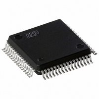
SAA7327H/T/M2B,557 NXP Semiconductors, SAA7327H/T/M2B,557 Datasheet - Page 21

SAA7327H/T/M2B,557
Manufacturer Part Number
SAA7327H/T/M2B,557
Description
IC DIGITAL/CD DAC DECODER 64QFP
Manufacturer
NXP Semiconductors
Type
Audio Decoderr
Datasheet
1.SAA7327HTM2B557.pdf
(68 pages)
Specifications of SAA7327H/T/M2B,557
Voltage - Supply, Digital
3 V ~ 3.6 V
Mounting Type
Surface Mount
Package / Case
64-QFP
Lead Free Status / RoHS Status
Lead free / RoHS Compliant
Applications
-
Voltage - Supply, Analog
-
Lead Free Status / RoHS Status
Lead free / RoHS Compliant, Lead free / RoHS Compliant
Other names
935268128557
SAA7327HBG
SAA7327HBG
SAA7327HBG
SAA7327HBG
Available stocks
Company
Part Number
Manufacturer
Quantity
Price
Company:
Part Number:
SAA7327H/T/M2B,557
Manufacturer:
NXP Semiconductors
Quantity:
10 000
Philips Semiconductors
7.10
The KILL circuit detects digital silence by testing for an
all-zero or all-ones data word in the left or right channel
prior to the digital filter. The output is switched active LOW
when silence has been detected for at least 270 ms, or if
mute is active, or in CD-ROM modes. Two modes are
available which can be selected by decoder register C:
It should be noted that when mute is active or in CD-ROM
modes the output(s) are switched LOW.
7.11
The audio features can be turned off (selected by decoder
register E) which affects the following functions:
Table 9 V2/V3 configuration
Table 10 Pin applications
2000 Jun 26
PIN NAME
SHADEN
Pin KILL: KILL active LOW indicates silence detected on
both left and right channels
Pin KILL: KILL active LOW indicates silence detected on
left channel. V3 active LOW indicates silence detected
on right channel.
Digital filter, fade, peak detector, KILL circuit (but
outputs KILL, V3 still active) are disabled
V5 (if selected to be the de-emphasis flag output) and
the EBU outputs become undefined.
Digital servo processor and Compact Disc
decoder with integrated DAC for video CD (CD7 II)
V1
V2
V3
V4
V5
1
KILL circuit
Audio features off
ADDRESS REGISTER
0011 (3H)
NUMBER
PIN
63
36
36
61
62
control of
V2/V3 pin
output
output
output
TYPE
input
input
REGISTER
ADDRESS
DATA
0XXX
1XXX
1100
1100
1101
1101
V2/V3 pin configured as V2 input
V2/V3 pin configured as V3 output (open-drain)
REGISTER
21
DATA
XXX1
XXX0
XX0X
X01X
X11X
XX01
XX10
XX11
01XX
10XX
11XX
0000
It should be noted that the EBU output should be set LOW
prior to switching the audio features off and after switching
audio features back on a full-scale command should be
given.
7.12
The SAA73727 has four pins that can be reconfigured for
different applications. One of these pins, V2/V3, can be
programmed as an input (V2) or as an output (V3). Control
of the V2/V3 pin is via shadow register 3; see Table 9:
Selection of the V2/V3 pin does not affect the function
programmed by decoder register C i.e. the V2/V3 pin can
be changed from V2 to V3 function either before or after
setting the desired function via decoder register 1100.
Selection of, for instance, a V3 function while the V2/V3
pin is set to V2 will not affect the V2 functionality.
The functions of these versatile pins is identical to the
SAA737x series. The functions of these versatile pins is
programmed by decoder registers C and D, as shown in
Table 10.
The VIA interface
external off-track signal input
internal off-track signal used input may be read
via decoder status bit; selected via register 2
input may be read via decoder status bit;
selected via register 2
KILL output for right channel
output = 0
output = 1
4-line motor drive (using V4 and V5)
Q to W subcode output
output = 0
output = 1
de-emphasis output (active HIGH)
output = 0
output = 1
FUNCTION
FUNCTION
Product specification
SAA7327
RESET
reset


