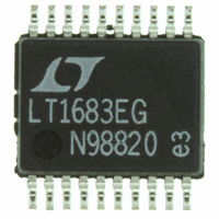
LTC1562CG-2#PBF Linear Technology, LTC1562CG-2#PBF Datasheet - Page 8

LTC1562CG-2#PBF
Manufacturer Part Number
LTC1562CG-2#PBF
Description
IC FILTER UNIV RC QUAD LN 20SSOP
Manufacturer
Linear Technology
Datasheet
1.LTC1562CG-2PBF.pdf
(16 pages)
Specifications of LTC1562CG-2#PBF
Filter Type
Universal, Continuous-Time
Frequency - Cutoff Or Center
300kHz
Number Of Filters
4
Max-order
8th
Voltage - Supply
4.75 V ~ 10.5 V, ±4.75 V ~ 5.25 V
Mounting Type
Surface Mount
Package / Case
20-SSOP
Lead Free Status / RoHS Status
Lead free / RoHS Compliant
Available stocks
Company
Part Number
Manufacturer
Quantity
Price
APPLICATIONS
LTC1562-2
tend to scale with R2.) At high f
4k, heavily loading the outputs of the LTC1562-2 and
leading to increased THD and other effects. At the other
extreme, a lower f
upper resistor limit of 1M . The LTC1562-2’s MOS input
circuitry can accommodate higher resistor values than
this, but junction leakage current from the input protection
circuitry may cause DC errors.
The 2nd order transfer functions H
H
the lowpass gain is – H
caded, these phase inversions cancel. Thus, the filter in the
application schematic on the first page of this data sheet
is a dual DC preserving, noninverting, rail-to-rail lowpass
filter, approximating two “straight wires with frequency
selectivity.”
Figure 4 shows further details of 2nd order lowpass,
bandpass and highpass responses. Configurations to
obtain these responses appear in the next three sections.
8
HP
(s) (below) are all inverting so that, for example, at DC
0.707 H
H
B
B
O
Q
f
f
U
L
H
BANDPASS RESPONSE
limit of 20kHz reflects an arbitrary
f
f
f
H
O
O
f (LOG SCALE)
f
–
O
2
f
2
–1
L
L
f
Q
1
Q
L
INFORMATION
. If two such sections are cas-
;
U
f
O
f
O
2
2
1
1
f f
Q
Q
L H
f
O
H
Figure 4. Characteristics of Standard 2nd Order Filter Responses
2
2
these resistors fall below
1
1
W
LP
(s), H
0.707 H
H
H
BP
U
P
L
L
(s) and
H
f
f
C
P
P
f
f
O
O
H
L
1
LOWPASS RESPONSE
1
Q
–
1
–
2
f (LOG SCALE)
2
Q
1
1
Q
1
2
1
–
Basic Lowpass
When Z
2nd order lowpass transfer function results from V
(Figure 5):
H
transfer function includes a sign inversion.) Parameters
2
4
L
Q
1
f
2
P
V s
V s
= R2/R
IN
2
1
–
f
( )
( )
C
2
IN
Q
1
2
of Figure 3 is a resistor of value R
2
IN
Figure 5. Basic Lowpass Configuration
H
1
LP
is the DC gain magnitude. (Note that the
V
IN
( )
s
0.707 H
R
IN
H
H
s
INV
H
H
P
2
1/4 LTC1562-2
2nd ORDER
H
f
f
P
C
V1
P
–
f
f
O
R
O
O
H
H
Q
H
L O
/
V2
1
Q
1
HIGHPASS RESPONSE
Q s
f
1
–
C
–
R2
2
2
1
2
Q
f (LOG SCALE)
1
1
–
Q
1562 F05
1
2
4
2
Q
1
–
1
2
f
P
V
2
O
OUT
1
–
IN
2
Q
1
, a standard
2
2
1
IN
1562-2 F04
–
1
to V2
15622fa


