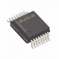
MAX1452AAE+ Maxim Integrated Products, MAX1452AAE+ Datasheet - Page 12

MAX1452AAE+
Manufacturer Part Number
MAX1452AAE+
Description
IC SENSOR SIGNAL COND 16-SSOP
Manufacturer
Maxim Integrated Products
Type
Signal Conditionerr
Datasheet
1.MAX1452CAE.pdf
(25 pages)
Specifications of MAX1452AAE+
Input Type
Analog
Output Type
Analog
Interface
Serial
Current - Supply
2.5mA
Mounting Type
Surface Mount
Package / Case
16-SSOP
Bandwidth
1.15MHz
Supply Voltage Min
4.5V
Supply Voltage Max
5.5V
Digital Ic Case Style
SSOP
No. Of Pins
16
Operating Temperature Range
-40°C To +125°C
Supply Voltage Range
4.5V To 5.5V
Rohs Compliant
Yes
Lead Free Status / RoHS Status
Lead free / RoHS Compliant
The ODAC and FSODAC are loaded from the EEPROM
lookup tables using an index pointer that is a function
of temperature. An ADC converts the integrated tem-
perature sensor output to an 8-bit value every 1ms. This
digitized value is then transferred into the temp-index
register.
The typical transfer function for the temp-index is as fol-
lows:
where temp-index is truncated to an 8-bit integer value.
Typical values for the temp-index register are given in
Table 6.
Note that the EEPROM is byte wide and the registers
that are loaded from EEPROM are 16 bits wide. Thus
each index value points to two bytes in the EEPROM.
Maxim programs all EEPROM locations to FFhex with
the exception of the oscillator frequency setting and
Secure-Lock byte. OSC[2:0] is in the Configuration
Register (Table 3). These bits should be maintained at
the factory preset values. Programming 00hex in the
Secure-Lock byte (CL[7:0] = 00hex), configures the
DIO as an asynchronous serial input for calibration and
test purposes.
The DIO serial interface is used for asynchronous serial
data communications between the MAX1452 and a
host calibration test system or computer. The MAX1452
automatically detects the baud rate of the host comput-
er when the host transmits the initialization sequence.
Baud rates between 4800bps and 38,400bps can be
detected and used regardless of the internal oscillator
frequency setting. Data format is always 1 start bit, 8
data bits, 1 stop bit and no parity. Communications are
only allowed when Secure-Lock is disabled (i.e.,
CL[7:0] = 00hex) or the UNLOCK pin is held high.
Sending the initialization sequence shown below
enables the MAX1452 to establish the baud rate that
initializes the serial port. The initialization sequence is
one byte transmission of 01hex, as follows:
The first start bit 0 initiates the baud rate synchronization
sequence. The 8 data bits 01hex (LSB first) follow this
and then the stop bit, which is indicated above as a 1,
terminates the baud rate synchronization sequence.
This initialization sequence on DIO should occur after a
period of 1ms after stable power is applied to the
device. This allows time for the power-on-reset function
Low-Cost Precision Sensor
Signal Conditioner
12
temp-index = 0.6879
______________________________________________________________________________________
1111111101000000011111111
Communication Protocol
✕
Initialization Sequence
Temperature (°C) + 44.0
to complete and the DIO pin to be configured by
Secure-Lock or the UNLOCK pin.
The MAX1452 allows for relearning the baud rate. The
reinitialization sequence is one byte transmission of
FFhex, as follows:
When a serial reinitialization sequence is received, the
receive logic resets itself to its power-up state and
waits for the initialization sequence. The initialization
sequence must follow the reinitialization sequence in
order to re-establish the baud rate.
All communication commands into the MAX1452 follow
a defined format utilizing an interface register set (IRS).
The IRS is an 8-bit command that contains both an
interface register set data (IRSD) nibble (4-bit) and an
interface register set address (IRSA) nibble (4-bit). All
internal calibration registers and EEPROM locations are
accessed for read and write through this interface reg-
ister set. The IRS byte command is structured as fol-
lows:
Where:
•
•
•
•
The IRS address decoding is shown in Table 10.
A special command register to internal logic
(CRIL[3:0]) causes execution of special command
sequences within the MAX1452. These command
sequences are listed as CRIL command codes as
shown in Table 11.
A 16-bit write to any of the internal calibration registers
is performed as follows:
1) Write the 16 data bits to DHR[15:0] using four byte
2) Write the address of the target internal calibration
IRSA[3:0] is the 4-bit interface register set address
and indicates which register receives the data nib-
ble IRSD[3:0].
IRSA[0] is the first bit on the serial interface after the
start bit.
IRSD[3:0] is the 4-bit interface register set data.
IRSD[0] is the fifth bit received on the serial inter-
face after the start bit.
accesses into the interface register set.
register to ICRA[3:0].
11111111011111111111111111
Serial Interface Command Format
IRS[7:0] = IRSD[3:0], IRSA[3:0]
Special Command Sequences
Reinitialization Sequence
Write Examples


