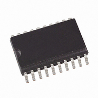
QT240-ISSG Atmel, QT240-ISSG Datasheet - Page 3

QT240-ISSG
Manufacturer Part Number
QT240-ISSG
Description
IC SENSOR QTOUCH 4CHAN 20SSOP
Manufacturer
Atmel
Series
Quantumr
Type
Signal Conditionerr
Datasheet
1.QT240-ISSG.pdf
(12 pages)
Specifications of QT240-ISSG
Input Type
Logic
Output Type
Logic
Current - Supply
1.5mA
Mounting Type
Surface Mount
Package / Case
20-SSOP
For Use With
427-1113 - BOARD EVAL FOR QT240-IS QTOUCH
Lead Free Status / RoHS Status
Lead free / RoHS Compliant
Interface
-
Other names
427-1102-2
QT240-ISS-G
QT240-ISS-G
Available stocks
Company
Part Number
Manufacturer
Quantity
Price
Part Number:
QT240-ISSG
Manufacturer:
ATMEL/爱特梅尔
Quantity:
20 000
1 Overview
1.1 Introduction
QT240 devices are burst mode digital charge-transfer (QT)
sensor ICs designed specifically for touch controls; they
include all hardware and signal processing functions
necessary to provide stable sensing under a wide variety of
conditions. Only a single low cost capacitor per channel is
required for operation.
Figures 1.1 and 1.2 show basic circuits for these device s.
See Table 1.1 for device pin listings.
The devices employ bursts of charge-transfer cycles to
acquire signals. Burst mode permits low power operation,
dramatically reduces RF emissions, lowers susceptibility to
RF fields, and yet permits excellent speed. Internally, signals
are digitally processed to reject impulse noise using a
'consensus' filter that requires six consecutive confirmations
of detection.
The QT switches and charge measurement hardware
functions are all internal to the device. A single-slope
switched capacitor ADC includes the QT charge and transfer
switches in a configuration that provides direct ADC
conversion; an external Cs capacitor accumulates the charge
from sense-plate Cx, which is then measured.
Larger values of Cx cause the charge transferred into Cs to
rise more rapidly, reducing available resolution; as a
minimum resolution is required for proper operation, this can
result in dramatically reduced gain. Larger values of Cs
reduce the rise of differential voltage across it, increasing
available resolution by permitting longer QT bursts. The
value of Cs can thus be increased to allow larger values of
Cx to be tolerated. The IC is responsive to both Cx and Cs,
and changes in either can result in substantial changes in
sensor gain.
Unused channels: If a channel is not used, a dummy sense
capacitor (nominal value 1nF ) of any type plus a 2.2K series
resistor must be connected between unused SNS pin pairs,
to ensure correct operation.
1.2 Operating Modes
The QT240 features spread-spectrum acquisition
capability, external synchronization of acquire
bursts, and fast and slow acquisition modes. These
modes are enabled via high-value resistors
connected to the SNS pins to ground or Vdd. These
resistors are required in every circuit.
There are two basic modes as shown in Figures 1.1
and 1.2.
Low-power Sync mode: In this mode the device
operates with about a 100ms response time and
very low current (about 90µA average at 4.0V). This
mode allows the device to be synchronized to an
external clock source, which can be used to either
suppress external interference (such as from
50/60Hz wiring) or to decrease response time
(which will also increase power consumption).
Spread-spectrum operation is not directly supported
in this mode. Sync usage is optional; the Sync pin
should be grounded if unused.
lQ
SPEED
OPT
S1
SYNC
3
OUT1
OUT2
OUT3
OUT4
VDD
Figure 1.1 Low Power, Synchronized Circuit
Fast, Spread-Spectrum mode: In this mode the device
operates with ~40ms response times but higher current drain
(~1.5mA @ 4.0V). This mode also supports spread-spectrum
operation via a few optional passive parts (if desired ). Sync
operation is not supported in this mode.
1.3 Electrode Drive; Wiring
The QT240 has four completely independent sensing
channels. The conversion process treats Cs on each channel
as a floating transfer capacitor; as a direct result, sense
electrodes can be connected to either SNS pin and the
sensitivity and basic function will be the same; however
electrodes should be connected to SNSnK lines to reduce
EMI susceptibility.
The PCB traces, wiring, and any components associated
with or in contact with either SNS pin will become touch
sensitive and should be treated with caution to limit the touch
area to the desired location.
R1
1M
Pin
10
11
12
13
14
15
16
17
18
19
20
1
2
3
4
5
6
7
8
9
22K
RSNS1
10nF
CS1
RS1
2.2K
Name
SYNC/SS
SNS2K
SNS1K
SNS4K
SNS3K
SNS2
SNS1
OUT1
OUT2
OUT3
OUT4
SNS4
SNS3
/RES
OSC
Table 1.1 Pin Listing - QT240-ISS
VSS
VDD
VSS
n.c.
n.c.
10nF
CS2
RS2
2.2K
22K
RSNS2
QT240-ISS
Description
Sense pin (to Rs2 + Cs2)
Sense pin (to Cs2, electrode)
Sense pin (to Rs1 + Cs1)
Sense pin (to Cs1, electrode); speed option
Output, key 1
Output, key 2
Output, key 3
Ground
Sync in and/or spread-spectrum drive
Unbonded internally
Unbonded internally
Output, key 4
Reset pin, active low. Can usually tie to Vdd.
Power: +4.0 to +5V locally regulated
Oscillator bias in
Ground or no connect
Sense pin (to Rs4 + Cs4)
Sense pin (to Cs4, electrode); OPT2
Sense pin (to Rs3 + Cs3)
Sense pin (to Cs3, electrode); OPT1
22K
RSNS3
10nF
CS3
RS3
2.2K
62K R4
QT240R R1.11/1006
22K
RSNS4
10nF
CS4
RS4
2.2K
10 second
timeout shown
VDD
1M
R3
OPT2
S3
OPT1
VDD
1M
S2
R2


