RE46C109E16F Microchip Technology, RE46C109E16F Datasheet - Page 6
RE46C109E16F
Manufacturer Part Number
RE46C109E16F
Description
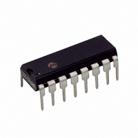
IC HORN DRIVER DUAL 16DIP
Manufacturer
Microchip Technology
Type
Driverr
Datasheet
1.RE46C109E16F.pdf
(9 pages)
Specifications of RE46C109E16F
Input Type
Logic
Output Type
Logic
Interface
Logic
Current - Supply
350µA
Mounting Type
Through Hole
Package / Case
16-DIP (0.300", 7.62mm)
Brief Features
Low Quiescent Current, Low Horn Driver Ron, Low Battery Detection Interface
Supply Voltage Range
6V To 12V
Operating Temperature Range
-40°C To +85°C
Digital Ic Case
RoHS Compliant
Product
Piezoelectric Horn Drivers
Ic Function
Piezoelectric Horn Driver & Voltage Regulator, Voltage Converter
Rohs Compliant
Yes
Lead Free Status / RoHS Status
Lead free / RoHS Compliant
Lead Free Status / RoHS Status
Lead free / RoHS Compliant


RE46C109
Voltage Regulator, Voltage Converter and
R&E International
Piezoelectric Horn Driver
A Subsidiary of Microchip Technology Inc.
Product Specification
Device Operation
(Please refer to the functional block diagram)
The RE46C109 consists of the following main functional blocks: band gap voltage reference, low drop-out voltage
regulator (with over voltage clamp and power supply brownout protection), low battery detection, switched
capacitor 12 volt boost regulator, horn driver and Interconnect logic.
When power is applied the band gap voltage reference and the voltage regulator output are initially enabled. The
low battery detection, horn driver outputs and switched capacitor 12v boost regulator are enabled by TTL
compatible positive logic control inputs.
When the HRNEN (Horn Enable) input is brought to a logic high level, the horn driver outputs as well as the 12v
boost regulator become active. The 12v boost regulator supplies the horn driver outputs. The 12v boost regulator
utilizes a charge pump to boost the Vdd supply input to a regulated 12-volt output. The charge pump consists of
an internal oscillator that is controlled in a voltage comparator feedback configuration.
The low battery detection is enabled and strobed when the LBST input is brought to a logic high level. The LBAT
output is a voltage follower amplifier whose input is determined by a resistor divider across the device supply rails.
© 2009 Microchip Technology Inc.
DS22168A-page 6
Related parts for RE46C109E16F
Image
Part Number
Description
Manufacturer
Datasheet
Request
R

Part Number:
Description:
Manufacturer:
Microchip Technology Inc.
Datasheet:
Part Number:
Description:
Manufacturer:
Microchip Technology Inc.
Datasheet:
Part Number:
Description:
Manufacturer:
Microchip Technology Inc.
Datasheet:
Part Number:
Description:
Manufacturer:
Microchip Technology Inc.
Datasheet:
Part Number:
Description:
Manufacturer:
Microchip Technology Inc.
Datasheet:
Part Number:
Description:
Manufacturer:
Microchip Technology Inc.
Datasheet:
Part Number:
Description:
Manufacturer:
Microchip Technology Inc.
Datasheet:
Part Number:
Description:
Manufacturer:
Microchip Technology Inc.
Datasheet: