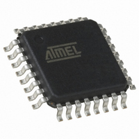
QT60248C-ASG Atmel, QT60248C-ASG Datasheet - Page 34

QT60248C-ASG
Manufacturer Part Number
QT60248C-ASG
Description
IC TOUCH SENSOR 24KEY 32TQFP
Manufacturer
Atmel
Series
QMatrix™, QProx™r
Type
Capacitiver
Specifications of QT60248C-ASG
Number Of Inputs/keys
24 Key
Resolution (bits)
9, 11 b
Data Interface
Serial, SPI™
Voltage - Supply
3 V ~ 5 V
Current - Supply
25mA
Operating Temperature
-40°C ~ 105°C
Mounting Type
Surface Mount
Package / Case
32-TQFP, 32-VQFP
Output Type
*
Interface
*
Input Type
*
For Use With
427-1087 - BOARD EVAL QT60248-AS QMATRIX
Lead Free Status / RoHS Status
Lead free / RoHS Compliant
Available stocks
Company
Part Number
Manufacturer
Quantity
Price
Company:
Part Number:
QT60248C-ASG
Manufacturer:
Atmel
Quantity:
5 700
10620D–AT42–04/09
Mutual-capacitance Zero-dimensional Sensors
4.2.2
4.2.2.1
4.2.2.2
4.2.2.3
4.2.2.4
4-2
X and Y Electrodes
Interdigitating the X and Y Electrodes
Width of Y Electrodes
Width of X Electrodes
Spacing Between the Electrodes
The X and Y electrodes are generally interdigitated, that is they form interlocking “fingers”. Typically the
X electrode surrounds the Y electrode, as it helps to contain the field between the two (see
Figure 4-2.
The Y electrodes should use the thinnest trace possible (say, 0.1 to 0.5 mm) for the Y fingers, as this
minimizes the possibility of noise coupling to the sensor during touch. Although past advice has
suggested Y trace widths as a function of T, extensive field testing has shown that a better SNR is
achieved using thinner traces.
For the X electrodes, wider electrodes are generally preferred as they tend to act as partial shields for
the Y traces. They also help maximize the free space coupling of small battery-powered products.
The width of the X fingers for the X electrodes should be calculated from thickness of the overlying
panel (T). Generally, the function T/2 is used, as shown in
As with the width of the X fingers, the spacing between the X and Y electrodes should be calculated from
thickness of the overlying panel (T). Again, the function T/2 is generally used, as shown in
T = Front panel thickness
* Y
constants rules (this is very important, for example, for ITO)
X
Y
(Typically
0.1–0.5 mm)*
width
border
width
Interdigitated X and Y Electrodes
is related to electrode conductivity. Keep Y line worst case resistance in line with RC time
³
T/2
T/2
T
X Electrode
T
W
T/2
T
Figure
Y Electrode
4-2.
T/2
Touch Sensors Design Guide
Figure
Figure
H
4-2.
4-2).


