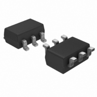
TB6078FUG(TE12L) Toshiba, TB6078FUG(TE12L) Datasheet - Page 7

TB6078FUG(TE12L)
Manufacturer Part Number
TB6078FUG(TE12L)
Description
IC AMP SHOCK SENSOR 8-SSOP
Manufacturer
Toshiba
Type
Sensor Interfacer
Datasheet
1.TB6078FUGTE12L.pdf
(14 pages)
Specifications of TB6078FUG(TE12L)
Package / Case
SOT-23-6
Mounting Type
Surface Mount
Current - Supply
3.9mA
Output Type
Voltage
Input Type
Voltage
Supply Voltage (max)
5.5 V
Supply Voltage (min)
2.7 V
Supply Current
3.5 mA
Maximum Operating Temperature
+ 85 C
Minimum Operating Temperature
- 25 C
Mounting Style
SMD/SMT
Product
Shock Sensor
Lead Free Status / RoHS Status
Lead free / RoHS Compliant
Interface
-
Lead Free Status / Rohs Status
Not Compliant
Other names
TB6078FUGTR
Available stocks
Company
Part Number
Manufacturer
Quantity
Price
Company:
Part Number:
TB6078FUG(TE12L)
Manufacturer:
MICREL
Quantity:
229
Application Note
Qs (pC/G)
sensor
Shock
Figure 1 shows the configuration of G-Force sensor amplifier.
The shock sensor is connected between the pins 1 and 16.
< How to output 0 or 1 from the pin 7 to detect whether there is a shock or not. >
a. Setting gain: C1 = C2 (pF), R1 (kΩ), R2 (kΩ)
b. Setting the frequency (Hz) of HPF: Setting C3 (µF), R1 (kΩ)
c. Setting the frequency (kHz) of LPF: Setting C4 (pF), R2 (kΩ)
< How to output the voltage according to the shock through the pin 5. >
a. Setting gain: C1 = C2 (pF), R1 (kΩ), R2 (kΩ)
Vsystem (mV/G). –
C1
C1
fc
fc
Qs
Qs
C1
– Using a sensor with the sensitivity Qs (pC/G) to detect the shock g (G). –
C1
– Using a sensor with the sensitivity Qs (pC/G), and assuming the shock sensitivity of the system is
(Hz)
(kHz)
=
=
×
×
16
1
Figure 1 The Configuration of G-Force Sensor Amplifier
g
C2
C2
2
×
×
=
=
=
50 MΩ
50 MΩ
=
2
5
2
C
C
×
×
Qs
Vsystem
2
×
1
2
0.04
5
×
R2
R1
π
Qs
×
×
π
×
15
2
g
R2
R1
×
1
R1
=
×
1
R2
Vsystem
R2
R1
×
=
×
×5
×
C3
0.4
C4
R2
R1
×
(V)
×
10 3
×
×
10
10 6
14
10 3
4
(pF)
(mV/G)
C
3
R
1
1.2 V
7
4
C1
C3
C4
C1
Example: Detecting 5 (G)-shock using a sensor
with Qs = 0.34 (pC/G), R1 = 10 (kΩ), R2 = 100 (kΩ).
Example: Setting the frequency to 20 Hz with
R1 = 10 (kΩ).
Example: Setting the frequency to 5 kHz with
R2 = 100 (kΩ).
Example: Designing the system with 200 (mV/G)
by using a sensor that Qs = 0.34 (pC/G),
R1 = 10 (kΩ), R2 = 100 (kΩ).
C
R
4
2
=
=
=
=
C2
C2
2
2
×
×
=
=
π
π
×
0.34
×
0.34
200
1
1
10
100
0.04
5
×
×
×
×
20
5
100
5
10
6
×
×
×
1.6 V
0.8 V
100
10 3
10 6
10
×
10
=
=
=
4
425
0.8
318
=
170
(
(pF)
µ
(pF)
F)
(pF)
TB6066FNG
2003-05-14
7


