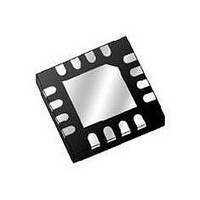
MPR083QR2 Freescale Semiconductor, MPR083QR2 Datasheet - Page 19

MPR083QR2
Manufacturer Part Number
MPR083QR2
Description
IC CTLR TOUCH SENSOR PROX 16-QFN
Manufacturer
Freescale Semiconductor
Type
Capacitiver
Datasheet
1.MPR083Q.pdf
(35 pages)
Specifications of MPR083QR2
Number Of Inputs/keys
8 Slider
Data Interface
I²C, Serial
Voltage - Supply
1.8 V ~ 3.6 V
Current - Supply
1.62mA
Operating Temperature
-40°C ~ 85°C
Mounting Type
Surface Mount
Package / Case
16-QFN Exposed Pad
Output Type
Voltage
Interface
I²C
Input Type
Logic
Supply Voltage
3.3 V
Dimensions
5 mm L x 5 mm W x 1 mm H
For Use With
DEMOMPR083 - BOARD DEMO FOR MPR083 CTLRKITMPR083EVM - KIT EVAL 8POSITION ROTARY TOUCH
Lead Free Status / RoHS Status
Lead free / RoHS Compliant
Sensors
Freescale Semiconductor
7
7.1
The MPR083 has one interrupt output that is configured by registers and alerts the application when a touch or fault is detected.
When running in Run2 or Stop2 mode where I
7.2
There are two cases that latch the Interrupt buffered data available or fault detected.
7.2.1
The interrupt for Buffered Data Available will only trigger when the NDF (No Data Flag) transitions from high to low. This signifies
that there is new data available in the buffer. The interrupt is deasserted on the first read/write of the FIFO Register and cannot
be reasserted for buffered data until the FIFO is empty (either by reading all the data, or clearing the buffer).
7.2.2
The interrupt for a fault detected condition is triggered any time the Fault condition in the Fault Register transitions from zero to
non-zero. The interrupt is deasserted when the Fault Register is cleared (by writing to the Fault Register).
7.3
Interrupts are configured through I
the interrupt functionality.
The Interrupt Enable (IRQEN) must be set high for the IRQ to be enabled. When low, all interrupts will be ignored, and the IRQ
pin will never latch.
The Interrupt Rate (IRQR) sets the minimum delay between sequential triggered interrupts. The minimum interrupt period can be
calculated by taking the product of the (MTP + 5) and IRQR with a factor of 4. Thus, for the minimum setting an interrupt would
be triggered no more often than 4 times the master clock.
If the MPR083 is using Run2, the minimum interrupt period would be represented by the following equation.
7.4
The IRQ pin is an open-drain, latching interrupt output which requires an external pull-up resistor. The pin will latch down based
on the conditions in
information about the source of the interrupt. Thus if the source is buffered data available then a FIFO Buffer read/write will clear
the IRQ pin. If the source is a fault detected then a write of the Fault Register will clear the pin.
Interrupts
Introduction
Condition for Interrupt
Buffered Data Available
Fault Detected
Settings
IRQ Pin
MinInterruptPeriod ms
Section
MinInterruptPeriod ms
6.2. The pin will reset when an I
2
C using the Configuration Register
2
C communication is not available this feature alerts the user to sensor touches.
=
MTP
--------------------- -
=
2
C transmission reads/writes the appropriate register displaying
MTP
8
+
5
(Section
+
+
5
1
IRQR
8 I
4.7). Two of the settings in this register will affect
RQR 4
4
Equation 4
Equation 5
MPR083
19


