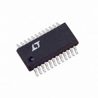
LTC1344ACG Linear Technology, LTC1344ACG Datasheet - Page 2

LTC1344ACG
Manufacturer Part Number
LTC1344ACG
Description
IC CABLE TERM MULTIPROTCL 24SSOP
Manufacturer
Linear Technology
Type
Cabler
Datasheet
1.LTC1344ACGPBF.pdf
(12 pages)
Specifications of LTC1344ACG
Number Of Terminations
6
Voltage - Supply
4.75 V ~ 5.25 V
Operating Temperature
0°C ~ 70°C
Mounting Type
Surface Mount
Package / Case
24-SSOP
Lead Free Status / RoHS Status
Contains lead / RoHS non-compliant
Available stocks
Company
Part Number
Manufacturer
Quantity
Price
Company:
Part Number:
LTC1344ACG
Manufacturer:
LTC
Quantity:
236
Part Number:
LTC1344ACG
Manufacturer:
LINEAR/凌特
Quantity:
20 000
Company:
Part Number:
LTC1344ACG#PBF
Manufacturer:
LTC
Quantity:
458
Part Number:
LTC1344ACG#PBF
Manufacturer:
LINEAR/凌特
Quantity:
20 000
Part Number:
LTC1344ACG#TRPBF
Manufacturer:
LT/凌特
Quantity:
20 000
ABSOLUTE
LTC1344A
(Note 1)
Positive Supply Voltage (V
Negative Supply Voltage (V
Input Voltage
(Logic Inputs) .................... (V
Input Voltage (Load Inputs) .................................. 18V
Power Dissipation .............................................. 600mW
Operating Temperature Range
Storage Temperature Range ................ – 65 C to 150 C
Lead Temperature (Soldering, 10 sec)................. 300 C
ELECTRICAL CHARACTERISTICS
V
The
temperature range.
Note 1: Absolute Maximum Ratings are those values beyond which the life
of a device may be impaired.
SYMBOL
Supplies
I
Terminator Pins
R
R
I
Logic Inputs
V
V
I
2
CC
LEAK
IN
IH
IL
CC
V.35
V.11
LTC1344AC ............................................ 0 C to 70 C
LTC1344AI ......................................... – 40 C to 85 C
= 5V 5%, V
denotes specifications which apply over the full operating
PARAMETER
Supply Current
Differential Mode Impedance
Common Mode Impedance
Differential Mode Impedance
High Impedance Leakage Current
Input High Voltage
Input Low Voltage
Input Current
EE
= – 5V 5%, T
W
MAXIMUM
CC
W W
EE
) ................................... 7V
A
) ........................... – 13.2V
= T
EE
MIN
– 0.3V) to (V
to T
RATINGS
CONDITIONS
All Digital Pins = GND or V
All Loads (Figure 1), – 2V V
All Loads (Figure 2), – 2V V
All Loads (Figure 1), – 2V V
All Loads (Figure 2), – 2V V
All Loads (Figure 1), V
All Loads (Figure 1), – 7V V
All Loads (Figure 1), V
All Loads (Figure 1), – 7V V
All Loads, – 7V V
All Logic Input Pins
All Logic Input Pins
All Logic Input Pins
MAX
(Notes 2, 3) unless otherwise noted.
U
CC
+ 0.3V)
CM
CM
CM
7V
= 0V (Commercial)
= 0V (Industrial)
CC
CM
CM
CM
CM
CM
CM
PACKAGE/ORDER I FOR ATIO
Consult factory for Military grade parts.
Note 2: All currents into device pins are positive; all currents out of device
pins are negative. All voltages are reference to ground unless otherwise
specified.
Note 3: All typicals are given at V
2V (Commercial)
2V (Commercial)
2V (Industrial)
2V (Industrial)
7V (Commercial)
7V (Industrial)
GND
R1C
R1B
R1A
R2A
R2B
R2C
R3A
R3B
R3C
V
M0
EE
T
JMAX
24-LEAD PLASTIC SSOP
10
11
12
1
2
3
4
5
6
7
8
9
= 150 C,
G PACKAGE
TOP VIEW
JA
= 100 C/W
24
23
22
21
20
19
18
17
16
15
14
13
CC
MIN
135
130
100
100
100
90
90
95
2
= 5V, V
M1
M2
DCE/DTE
LATCH
R6B
R6A
R5A
R5B
R4A
R4B
V
GND
CC
U
EE
TYP
104
153
104
153
104
104
104
104
0.4
= – 5V, T
1
ORDER PART
LTC1344ACG
LTC1344AIG
W
MAX
A
110
165
115
170
110
115
1.0
0.8
NUMBER
= 25 C.
50
10
UNITS
U
mA
A
V
V
A


