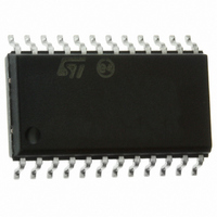
STLED316SMTR STMicroelectronics, STLED316SMTR Datasheet - Page 18

STLED316SMTR
Manufacturer Part Number
STLED316SMTR
Description
IC LED CTLR SERIAL 6DIGIT SO-24
Manufacturer
STMicroelectronics
Datasheet
1.STLED316SMTR.pdf
(33 pages)
Specifications of STLED316SMTR
Applications
LED Controller with Keyscan, 6-Digit
Interface
Serial
Voltage - Supply
4.5 V ~ 5.5 V
Package / Case
24-SOIC (7.5mm Width)
Mounting Type
Surface Mount
Number Of Digits
6
Number Of Segments
48
Operating Supply Voltage
4.5 V to 5.5 V
Maximum Supply Current
15000 uA
Maximum Power Dissipation
1200 mW
Maximum Operating Temperature
+ 85 C
Mounting Style
SMD/SMT
Minimum Operating Temperature
- 40 C
For Use With
497-8417 - BOARD DEMO FRONT PANEL STLED316S497-8399 - BOARD EVAL ST7LITE49M/STLED316S497-8432 - BOARD LED CTLR/DVR STLED316S
Lead Free Status / RoHS Status
Lead free / RoHS Compliant
Other names
497-6925-2
STLED316SMTR
STLED316SMTR
Available stocks
Company
Part Number
Manufacturer
Quantity
Price
Company:
Part Number:
STLED316SMTR
Manufacturer:
TE
Quantity:
17 600
Part Number:
STLED316SMTR
Manufacturer:
ST
Quantity:
20 000
Company:
Part Number:
STLED316SMTR#Y4
Manufacturer:
MICROCHIP
Quantity:
1 430
Key matrix and key-input data storage ram
7
18/33
Key matrix and key-input data storage ram
During the key scan cycle all the grids are turned off. The first segments turn on is 64 µs.
The key1 and key2 signals will be sampled after 60 µs. The two signals latch into the
internal key buffer. The same applies for other segments.
This key buffer compares the data with the previous key status. If any changes are seen in
the buffer values, then the IRQ_N is asserted. The IRQ_N signal is active low (level). This
IRQ_N signal will be cleared at the end of reading the key buffer (end of byte transfer). The
key buffer must be completely read before the IRQ_N is cleared.
The key matrix is of 8 x 2 configuration, as shown below:
Figure 4.
The data of each key are stored as illustrated below, and are read by the appropriate read
command, starting from the least significant bit.
1
2
The initial key buffer value is “00”. During operation, the buffer values will change depending
upon the values of the key-press.
st
nd
SEG1/KS1
SEG1/KS1
KEY1
KEY2
byte
LSB
LSB
byte
Key matrix
SEG2/KS2
SEG2/KS2
KEY1
KEY2
SEG3/KS3
SEG3/KS3
KEY1
KEY2
SEG4/KS4
SEG4/KS4
KEY1
KEY2
SEG5/KS5
SEG5/KS5
KEY1
KEY2
SEG6/KS6
SEG6/KS6
KEY1
KEY2
SEG7/KS7
SEG7/KS7
KEY1
KEY2
STLED316S
SEG8/KS8
SEG8/KS8
KEY1
KEY2
MSB
MSB


