LNBK20PD-TR STMicroelectronics, LNBK20PD-TR Datasheet - Page 3
LNBK20PD-TR
Manufacturer Part Number
LNBK20PD-TR
Description
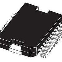
IC LNB SUPPLY & CNTRL 20-PWRSOIC
Manufacturer
STMicroelectronics
Datasheet
1.LNBK20PD.pdf
(25 pages)
Specifications of LNBK20PD-TR
Interface
Parallel
Voltage - Supply
15 V ~ 27 V
Package / Case
PowerSO-20 Exposed Bottom Pad
Mounting Type
Surface Mount
Polarity
Positive
Number Of Outputs
2
Output Type
Selectable
Output Voltage
13 V, 18 V
Line Regulation
50 mV
Load Regulation
150 mV
Input Voltage Max
28 V
Maximum Operating Temperature
+ 125 C
Minimum Operating Temperature
- 40 C
Maximum Power Dissipation
14000 mW
Mounting Style
SMD/SMT
Lead Free Status / RoHS Status
Lead free / RoHS Compliant
Applications
-
Lead Free Status / Rohs Status
Lead free / RoHS Compliant
Available stocks
Company
Part Number
Manufacturer
Quantity
Price


LNBK20
1
Description (continued)
For slave operation in single dish, dual receiver systems, the bypass function is
implemented by an electronic switch between the Master Input pin (MI) and the LNBA pin,
thus leaving all LNB powering and control functions to the Master Receiver. This electronic
switch is closed when the device is powered and EN pin is LOW.
The regulator outputs can be logic controlled to be 13 or 18 V (typ.) by mean of the VSEL
pin for remote controlling of LNBs. Additionally, it is possible to increment by 1V (typ.) the
selected voltage value to compensate the excess voltage drop along the coaxial cable (LLC
pin HIGH).
In order to reduce the power dissipation of the device when the lowest output voltage is
selected, the regulator has two Supply Input pins V
respectively at 16V (min) and 23V (min), and an internal switch automatically will select the
suitable supply pin according to the selected output voltage. If adequate heatsink is
provided and higher power losses are acceptable, both supply pins can be powered by the
same 23V source without affecting any other circuit performance.
The ENT (Tone Enable) pin activates the internal oscillator so that the DC output is
modulated by a ±0.3 V, 22KHz (typ.) square wave. This internal oscillator is factory trimmed
within a tolerance of ±2KHz, thus no further adjustments neither external components are
required.
A burst coding of the 22KHz tone can be accomplished thanks to the fast response of the
ENT input and the prompt oscillator start-up. This helps designers who want to implement
the DiSEqC
In order to improve design flexibility and to allow implementation of newcoming LNB remote
control standards, an analogic modulation input pin is available (EXTM). An appropriate DC
blocking capacitor must be used to couple the modulating signal source to the EXTM pin.
When external modulation is not used, the relevant pin can be left open.
Two pins are dedicated to the overcurrent protection/monitoring: CEXT and OLF. The
overcurrent protection circuit works dynamically: as soon as an overload is detected in
either LNB output, the output is shut-down for a time T
connected between CEXT and GND. Simultaneously the OLF pin, that is an open collector
diagnostic output flag, from HIGH IMPEDANCE state goes LOW.
After the time has elapsed, the output is resumed for a time t
in HIGH IMPEDANCE. If the overload is still present, the protection circuit will cycle again
through t
4.7µF external capacitor is used.
This dynamic operation can greatly reduce the power dissipation in short circuit condition,
still ensuring excellent power-on start up even with highly capacitive loads on LNB outputs.
The device is packaged in PowerSO-20 for surface mounting. When a limited functionality in
a smaller package matches design needs, a range of cost-effective PowerSO-10 solutions is
also offered. All versions have built-in thermal protection against overheating damage.
a. External components are needed to comply to level 2.x and above (bidirectional) DiSEqC
requirements. DiSEqC
off
and t
TM
protocols
on
until the overload is removed. Typical t
TM
is a trademark or EUTELSAT.
(a)
.
CC1
off
and V
determined by the capacitor
on
+t
on
CC2
off
=1/15t
value is 1200ms when a
. They must be powered
Description (continued)
off
(typ.) and OLF goes
TM
bus hardware
3/25
Related parts for LNBK20PD-TR
Image
Part Number
Description
Manufacturer
Datasheet
Request
R

Part Number:
Description:
Lnb Supply And Control Voltage Regulator Parallel Interface
Manufacturer:
STMicroelectronics
Datasheet:
Part Number:
Description:
STMicroelectronics [RIPPLE-CARRY BINARY COUNTER/DIVIDERS]
Manufacturer:
STMicroelectronics
Datasheet:
Part Number:
Description:
STMicroelectronics [LIQUID-CRYSTAL DISPLAY DRIVERS]
Manufacturer:
STMicroelectronics
Datasheet:

Part Number:
Description:
BOARD EVAL FOR MEMS SENSORS
Manufacturer:
STMicroelectronics
Datasheet:
Part Number:
Description:
NPN TRANSISTOR POWER MODULE
Manufacturer:
STMicroelectronics
Datasheet:
Part Number:
Description:
TURBOSWITCH ULTRA-FAST HIGH VOLTAGE DIODE
Manufacturer:
STMicroelectronics
Datasheet:
Part Number:
Description:
Manufacturer:
STMicroelectronics
Datasheet:
Part Number:
Description:
DIODE / SCR MODULE
Manufacturer:
STMicroelectronics
Datasheet:
Part Number:
Description:
DIODE / SCR MODULE
Manufacturer:
STMicroelectronics
Datasheet:
Part Number:
Description:
Search -----> STE16N100
Manufacturer:
STMicroelectronics
Datasheet:
Part Number:
Description:
Search ---> STE53NA50
Manufacturer:
STMicroelectronics
Datasheet:
Part Number:
Description:
NPN Transistor Power Module
Manufacturer:
STMicroelectronics
Datasheet: