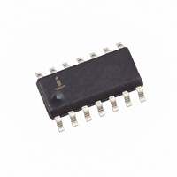
HA4314BCB Intersil, HA4314BCB Datasheet - Page 4

HA4314BCB
Manufacturer Part Number
HA4314BCB
Description
IC VIDEO CROSSPOINT SWIT 14SOIC
Manufacturer
Intersil
Datasheet
1.HA4314BCB.pdf
(12 pages)
Specifications of HA4314BCB
Function
Video Crosspoint Switch
Circuit
1 x 4:1
Voltage Supply Source
Dual Supply
Voltage - Supply, Single/dual (±)
±4.5 V ~ 5.5 V
Current - Supply
400µA
Operating Temperature
0°C ~ 70°C
Mounting Type
Surface Mount
Package / Case
14-SOIC (0.154", 3.90mm Width)
Lead Free Status / RoHS Status
Contains lead / RoHS non-compliant
Available stocks
Company
Part Number
Manufacturer
Quantity
Price
Company:
Part Number:
HA4314BCB
Manufacturer:
INTEL
Quantity:
2 500
Part Number:
HA4314BCB
Manufacturer:
HARRIS
Quantity:
20 000
Company:
Part Number:
HA4314BCB96
Manufacturer:
INTERSIL
Quantity:
2 500
Company:
Part Number:
HA4314BCBZ
Manufacturer:
Intersil
Quantity:
200
Company:
Part Number:
HA4314BCBZ
Manufacturer:
Intersil
Quantity:
95
Part Number:
HA4314BCBZ
Manufacturer:
INTERSIL
Quantity:
20 000
Electrical Specifications
NOTES:
AC Test Circuit
NOTE: C
-3dB Bandwidth
±0.1dB Flat Bandwidth
Input Resistance
Input Capacitance
Enabled Output Resistance
Disabled Output Capacitance
Differential Gain
Differential Phase
Off Isolation
Crosstalk Rejection
Slew Rate (1.5V
Total Harmonic Distortion
Disabled Output Resistance
3. Limits should be considered typical and are not production tested.
4. Parts are 100% tested at +25°C. Over-temperature limits established by characterization and are not production tested.
V
IN
75Ω
L
= C
HA4314
PARAMETER
X
P-P
+ Test Fixture Capacitance.
, +SR/-SR)
R
S
500Ω
C
X
400Ω
4
10kΩ
V
SUPPLY
510Ω
-
+
HFA1100
R
R
R
R
R
R
R
R
V
4.43MHz, (Note 3)
4.43MHz, (Note 3)
1V
R
1V
R
R
R
R
10MHz, R
V
= ±5V, R
CS
CS
S
S
S
S
S
S
S
S
L
S
S
S
S
P-P
P-P
= 10Ω
= 50Ω, C
= 20Ω, C
= 16Ω, C
= 13Ω, C
= 50Ω, C
= 20Ω, C
= 16Ω, C
= 13Ω, C
= 50Ω, C
= 20Ω, C
= 16Ω, C
= 13Ω, C
TEST CONDITIONS
= 2.0V
= 2.0V
, 100MHz, V
, 30MHz
75Ω
L
L
= 10kΩ, V
= 1kΩ, (Note 3)
L
L
L
L
L
L
L
L
L
L
L
L
= 10pF
= 20pF
= 36pF
= 49pF
= 10pF
= 20pF
= 36pF
= 49pF
= 10pF
= 20pF
= 36pF
= 49pF
V
OUT
CS
HA4314B
CS
= 2.0V,
= 0.8V, Unless Otherwise Specified. (Continued)
PC Board Layout
The frequency response of this circuit depends greatly on
the care taken in designing the PC board. The use of low
inductance components such as chip resistors and chip
capacitors is strongly recommended, while a solid
ground plane is a must!
Attention should be given to decoupling the power supplies.
A large value (10µF) tantalum in parallel with a small value
(0.1µF) chip capacitor works well in most cases.
Keep input and output traces as short as possible, because
trace inductance and capacitance can easily become the
performance limiting items.
TEMP. (°C)
Full
Full
Full
Full
Full
Full
Full
Full
25
25
25
25
25
25
25
25
25
25
25
25
25
25
(Note 4)
MIN
200
-
-
-
-
-
-
-
-
-
-
-
-
-
-
-
-
-
-
-
-
-
1425/1450
1010/1010
725/750
600/650
TYP
0.01
0.01
0.01
400
280
140
110
100
100
400
1.5
2.5
85
75
15
70
80
12
(Note 4)
MAX
0.02
0.02
0.1
-
-
-
-
-
-
-
-
-
-
-
-
-
-
-
-
-
-
-
September 11, 2007
UNITS
FN3679.12
MHz
MHz
MHz
MHz
MHz
MHz
MHz
MHz
V/µs
V/µs
V/µs
V/µs
MΩ
kΩ
pF
pF
dB
dB
%
%
Ω
°


