GP1UE27XK Sharp Microelectronics, GP1UE27XK Datasheet

RECEIVER IR REM CTRL 3V 40KHZ

GP1UE27XK

Manufacturer Part Number
GP1UE27XK
Description
RECEIVER IR REM CTRL 3V 40KHZ
Manufacturer
Sharp Microelectronics
Datasheet

Specifications of GP1UE27XK

Sensing Distance
10m
B.p.f. Center Frequency
40.0kHz
Voltage - Supply
2.4 V ~ 3.6 V
Current - Supply
600µA
Orientation
Top View
Mounting Type
Through Hole
Lead Free Status / Rohs Status
Contains lead / RoHS non-compliant
Other names
425-1904

Available stocks

Company
Part Number
Manufacturer
Quantity
Price
Part Number:
GP1UE27XK
Manufacturer:
SHARP
Quantity:
1
Part Number:
GP1UE27XK0VF
Manufacturer:
SHARP
Quantity:
2 960
GP1UE26XK/GP1UE27XK Series
GP1UE28XK/GP1UE28YK Series
1. Low dissipation current:MAX. 0.6mA(at V
2. Low operating voltage:2.4 to 3.6V
3. Compact (case volume).
4. Various B.P.F. (Band Pass Frequency) frequency to meet different user needs.
GP1UE26XK Series
Notice
Internet Internet address for Electronic Components Group http://sharp-world.com/ecg/
Outline Dimensions
1.*1 : Indicates root dimensions of connector.
2.Unspecified tolerance : 0.3
3.Case thickness : 0.3TYP
4.*2 : Exclude sagged solder
5.*3 : If there are difficulties to insert the GP1UE26XK series on PCB,
Features
1.25
*1
0.7
2.54
0.5
Example of mounting drawing from solder side (Reference)
we recommend to expand 0.1mm from original 2.9mm.
1
In the absence of confirmation by device specification sheets, SHARP takes no responsibility for any defects that may occur in equipment using any SHARP
devices shown in catalogs, data books, etc. Contact SHARP in order to obtain the latest device specification sheets before using any SHARP device.
5.6
1
2
3
2 3
V
V
GND
OUT
CC
*1
1.25
2.54
0.7
Center of PD
1.8
R2.1
5
8.6
*3
2.54
1.4
0.5
2.9
3.6
CC
3
*2
*3
3.6
5.8
3V)
2
0.5
1
2.54
2.9
1.4
*3
GP1UE27XK Series
1.25
*1
1.*1 : Indicates root dimensions of connector.
2.Unspecified tolerance : 0.3
3.Case thickness : 0.3TYP
4.*2 : Exclude sagged solder
5.*3 : If there are difficulties to insert the GP1UE27XK series on PCB,
Low Voltage Operation,
Compact IR Detecting Unit
for Remote Control
1. AV equipments
2. Home appliances
2.54
0.8
0.5
Applications
Example of mounting drawing from solder side (Reference)
we recommend to expand 0.1mm from original 2.9mm.
1
1
2
3
5.6
2 3
V
V
GND
GP1UE26XK/27XK/28XK/28YK Series
OUT
CC
*1
1.25
2.54
0.8
Center of PD
1.8
R2.1
10.2
*2
13.8
3.6
*3
2.54
1.4
0.5
0.5
2.9
3.6
3
*3
5.8
2
(Unit : mm)
1
2.54
2.9
1.4
*3

Related parts for GP1UE27XK

GP1UE27XK Summary of contents

Page 1

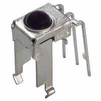
... GND Example of mounting drawing from solder side (Reference) 1.*1 : Indicates root dimensions of connector. 2.Unspecified tolerance : 0.3 3.Case thickness : 0.3TYP 4.*2 : Exclude sagged solder 5.* there are difficulties to insert the GP1UE27XK series on PCB, we recommend to expand 0.1mm from original 2.9mm. (Unit : mm) 1.25 1.8 10.2 3 ...

Page 2

... Indicates root dimensions of connector. 2.54 2.54 2.Unspecified tolerance : 0.3 3.Case thickness : 0.3TYP 4.*2 : Exclude sagged solder 5.* there are difficulties to insert the GP1UE28YK series on PCB, we recommend to expand 0.1mm from original 2.9mm. Model No. GP1UE27XK GP1UE270XK GP1UE271XK GP1UE272XK GP1UE277XK GP1UE26XK/27XK/28XK/28YK Series 1.8 2.75 5.6 R2 ...

Page 3

Internal Block Diagram Absolute Maximum Ratings Parameter Symbol Supply voltage Operating temperature T opr Storage temperature T stg *2 Soldering temperature T sol *1 No dew condensation is allowed *2 For 5s (At mounting on PCB with ...

Page 4

Performance Using the transmitter shown in Fig. 1, the output signal of the light detecting unit is good enough to meet the following items in the standard optical system in Fig Linear reception distance characteristics *7 *5 When ...

Page 5

Precautions for Operation 1. When this infrared remote control detecting unit shall be adopted for wireless remote control, please use it with the signal format of transmitter, which total duty ratio D (Pulse width of the presence of modulated IR) ...

Page 6

There is a possibility that noise on output may be caused by environmental condition (Disturbing light noise, Electromagnetic noise, Power supply line noise, etc.) even if there is no input transmission signal. 11. Please shall confirm operation or your ...

Page 7

NOTICE G The circuit application examples in this publication are provided to explain representative applications of SHARP devices and are not intended to guarantee any circuit design or license any intellectual property rights. SHARP takes no responsibility for any problems ...

Related keywords