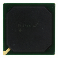
EL4544IGZ Intersil, EL4544IGZ Datasheet - Page 25

EL4544IGZ
Manufacturer Part Number
EL4544IGZ
Description
IC CROSSPOINT VID 16X5RGB 356BGA
Manufacturer
Intersil
Datasheet
1.EL4544IGZ.pdf
(26 pages)
Specifications of EL4544IGZ
Function
Crosspoint Switch
Circuit
3 x 16:5
Voltage Supply Source
Single Supply
Voltage - Supply, Single/dual (±)
4.75 V ~ 5.25 V, 2.4 V ~ 3.6 V
Operating Temperature
-40°C ~ 85°C
Mounting Type
Surface Mount
Package / Case
356-PBGA
Rohs Compliant
YES
Lead Free Status / RoHS Status
Lead free / RoHS Compliant
Available stocks
Company
Part Number
Manufacturer
Quantity
Price
Company:
Part Number:
EL4544IGZ
Manufacturer:
Intersil
Quantity:
800
Part Number:
EL4544IGZ
Manufacturer:
INTERSIL
Quantity:
20 000
is in parallel with the external termination network, it has a
consistent effect on the system gain. To maintain this
consistency, it is inadvisable to program more than one input
stage (Ai, Bi, Ci, or Di) to "look" at any given video input
(RGB0, RGB1, …, RGBF) since each activated input stage
puts an additional parallel load of 3.5kΩ onto the selected
input. When programming the serial interface this is simply
expressed as: Avoid programming the same value into the
four data registers (for Ai, Bi, Ci, and Di) at hex addresses
0H, 1H, 2H, and 3H. They should all have unique values.
This is important since if any inputs are selected more than
once, their gains will mismatch an input that has only been
selected once.
If one wishes to broadcast the same signal to multiple output
channels, this can easily be accomplished without violating
the advice of the previous paragraph. Select the input that
needs to be broadcast using any one of the four input
selectors (Ai, Bi, Ci, or Di), then have any of up to five of the
output stages (Ax, Bx, Cx, Dx, Sx) point to the input stage
that is pointing to the desired input signal. These are
selected using hex 8H, 9H, AH, BH, and CH. Now the
EL4544 is broadcasting a single video source to multiple
outputs without excessively loading down the selected input.
Sync Decoding of EL4544
The EL4544 is designed to receive and decode Horizontal
and Vertical Sync signals that have been encoded as
common-mode signals of the Red, Green, and Blue Video
inputs. The EL4543 provides this encoding as shown in
Table 1.
Intersil products are sold by description only. Intersil Corporation reserves the right to make changes in circuit design, software and/or specifications at any time without
notice. Accordingly, the reader is cautioned to verify that data sheets are current before placing orders. Information furnished by Intersil is believed to be accurate and
reliable. However, no responsibility is assumed by Intersil or its subsidiaries for its use; nor for any infringements of patents or other rights of third parties which may result
from its use. No license is granted by implication or otherwise under any patent or patent rights of Intersil or its subsidiaries.
High
High
Low
Low
H
TABLE 1. SYNC SIGNAL ENCODING
All Intersil U.S. products are manufactured, assembled and tested utilizing ISO9000 quality systems.
High
High
Low
Low
V
Intersil Corporation’s quality certifications can be viewed at www.intersil.com/design/quality
For information regarding Intersil Corporation and its products, see www.intersil.com
COMMON
MODE A
(RED)
2.5
25
3.0
2.5
2.0
COMMON
(GREEN)
MODE B
2.0
2.0
3.0
3.0
COMMON
MODE C
(BLUE)
2.5
2.5
3.0
2.0
EL4544
The EL4544 decodes the common-mode signals into H and
V syncs as follows: Horizontal Sync is TRUE when the
Blue_Common_Mode voltage is greater than the
Average_of_Red_and_Green_Common_Mode voltage.
Vertical Sync is TRUE when the
Average_of_Red_and_Blue_Common_Mode voltage is
greater than the Green_Common_Mode voltage. The sync
comparators have an internal symmetrical hysteresis that is
less than ±50mV. Timing skews between comparators under
all conditions are less than one pixel. The comparators have
an input common mode that allows for operation at least 1V
from the negative supplies and at least 1.5V from the
positive supplies.
Logic Levels for Serial Interface and Control Logic
TABLE 2. INPUT LOGIC THRESHOLD (+5V SUPPLY)
V
V
LO
HI
, max
, min
0.8V
2V
December 21, 2007
FN7362.4


