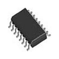
SI3201-GSR Silicon Laboratories Inc, SI3201-GSR Datasheet - Page 36

SI3201-GSR
Manufacturer Part Number
SI3201-GSR
Description
SLIC 3.3V/3.3V/3.3V/5V/5V/5V
Manufacturer
Silicon Laboratories Inc
Datasheet
1.SI3201-GSR.pdf
(122 pages)
Specifications of SI3201-GSR
Lead Free Status / Rohs Status
Compliant
- Current page: 36 of 122
- Download datasheet (730Kb)
Si3216
2.2.5. DC-DC Converter Enhancements
The ProSLIC supports two selectable enhancements to
the dc-dc converter. The first is a multi-threshold error
control algorithm that enables the dc-dc converter to
adjust more quickly to voltage changes. This option is
enabled by setting DCSU = 1 (direct Register 108,
bit 5). The second enhancement is an audio band filter
that removes audio band noise from the dc-dc converter
control loop. This option is enabled by setting DCFIL = 1
(direct Register 108, bit 1).
2.2.6. DC-DC Converter During Ringing
When the ProSLIC enters the Ringing state, it requires
voltages well above those used in the active mode. The
voltage to be generated and regulated by the dc-dc
converter during a ringing burst is set using the V
register (direct Register 74). V
0 and –94.5 V in 1.5 V steps. To avoid clipping the
ringing signal, V
amplitude. At the end of each ringing burst the dc-dc
converter adjusts back to active state regulation as
36
Counter
Modulo
16-Bit
*Tone Generator 1 Only
n = "1" or "2" for Tone Generator 1 and 2, respectively
OATn
8 kHz
Clock
OITn
BATH
OATnE
OITnE
must be set larger than the ringing
Expire
Expire
OAT
OIT
OnE
Figure 20. Simplified Tone Generator Diagram
BATH
Cross
Logic
Zero
Logic
Logic
INT
INT
can be set between
OZn
Zero Cross
OSSn
Logic
Load
OnAE
OnAP
OnIE
OnIP
REL*
BATH
Register
Enable
Rev. 1.0
Load
Resonance
described above.
2.3. Tone Generation
Two digital tone generators are provided in the ProSLIC.
They allow the generation of a wide variety of single or
dual tone frequency and amplitude combinations and
spare the user the effort of generating the required
POTS signaling tones on the PCM highway. DTMF, FSK
(caller ID), call progress, and other tones can all be
generated on-chip. The tones can be sent to either the
receive or transmit paths. (See Figure 24 on page 44.)
2.3.1. Tone Generator Architecture
A simplified diagram of the tone generator architecture
is shown in Figure 20. The oscillator, active/inactive
timers, interrupt block, and signal routing block are
connected to give the user flexibility in creating audio
signals. Control and status register bits are placed in the
figure to indicate their association with the tone
generator architecture. These registers are described in
more detail in Table 28 on page 38.
Two-Pole
Oscillator
16 kHz
Clock
OSCnX
OSCnY
OSCn
Routing
Signal
OnSO
to RX Path
to TX Path
Related parts for SI3201-GSR
Image
Part Number
Description
Manufacturer
Datasheet
Request
R

Part Number:
Description:
IC LINEFEED INTRFC SI321X 16SOIC
Manufacturer:
Silicon Laboratories Inc
Datasheet:

Part Number:
Description:
IC LINEFEED INTRFC SI321X 16SOIC
Manufacturer:
Silicon Laboratories Inc
Datasheet:

Part Number:
Description:
IC LINEFEED INTRFC SI321X 16SOIC
Manufacturer:
Silicon Laboratories Inc
Datasheet:

Part Number:
Description:
IC LINEFEED INTRFC SI321X 16SOIC
Manufacturer:
Silicon Laboratories Inc
Datasheet:
Part Number:
Description:
SLIC 1-CH 60dB 41mA 3.3V/5V 16-Pin SOIC EP T/R
Manufacturer:
Silicon Laboratories Inc
Datasheet:
Part Number:
Description:
Manufacturer:
Silicon Laboratories Inc
Datasheet:

Part Number:
Description:
SWITCH,DC-MAIN,ESTOP,32A
Manufacturer:
IMO PRECISION CONTROLS
Datasheet:

Part Number:
Description:
SWITCH,DISCONNECT,32A,DC
Manufacturer:
IMO PRECISION CONTROLS
Datasheet:
Part Number:
Description:
SMD/C�/SINGLE-ENDED OUTPUT SILICON OSCILLATOR
Manufacturer:
Silicon Laboratories Inc
Part Number:
Description:
Manufacturer:
Silicon Laboratories Inc
Datasheet:
Part Number:
Description:
N/A N/A/SI4010 AES KEYFOB DEMO WITH LCD RX
Manufacturer:
Silicon Laboratories Inc
Datasheet:
Part Number:
Description:
N/A N/A/SI4010 SIMPLIFIED KEY FOB DEMO WITH LED RX
Manufacturer:
Silicon Laboratories Inc
Datasheet:
Part Number:
Description:
N/A/-40 TO 85 OC/EZLINK MODULE; F930/4432 HIGH BAND (REV E/B1)
Manufacturer:
Silicon Laboratories Inc


