ISD5116SY Nuvoton Technology Corporation of America, ISD5116SY Datasheet - Page 22

ISD5116SY
Manufacturer Part Number
ISD5116SY
Description
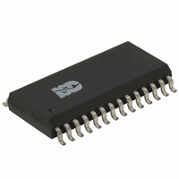
IC VOICE REC/PLAY 8-16MN 28-SOIC
Manufacturer
Nuvoton Technology Corporation of America
Series
ISD5100r
Datasheet
1.ISD5116SY.pdf
(90 pages)
Specifications of ISD5116SY
Interface
I²C
Filter Pass Band
1.7 ~ 3.4kHz
Duration
8 ~ 16 Min
Mounting Type
Surface Mount
Package / Case
28-SOIC (0.300", 7.50mm Width)
For Use With
ISD-ES511 - EVALUATION SYSTEM FOR ISD5100ISD-ES501 - EVALUATION SYSTEM FOR ISD5008
Lead Free Status / RoHS Status
Lead free / RoHS Compliant
Available stocks
Company
Part Number
Manufacturer
Quantity
Price
Company:
Part Number:
ISD5116SY
Manufacturer:
Intersil
Quantity:
649
Part Number:
ISD5116SY
Manufacturer:
ISD
Quantity:
20 000
Record Mode
The command sequence for an Analog Record would be a four byte sequence consisting of the Slave
Address (80h), the Command Byte (91h) for Record Analog @ Address, and the two address bytes.
See
The previous examples were dependent upon the device already being powered up and the various
paths being set through the device for the desired operation. To set up the device for the various
paths requires loading the two 16-bit Configuration Registers with the correct data. For example, in
the Feed Through Mode the device only needs to be powered up and a few paths selected.
This mode enables the ISD5100 Series to connect to a cellular or cordless base band phone chip set
without affecting the audio source or destination. There are two paths involved, the transmit path and
the receive path. The transmit path connects the Nuvoton chip’s microphone source through to the
microphone input on the base band chip set. The receive path connects the base band chip set’s
speaker output through to the speaker driver on the Nuvoton chip. This allows the Nuvoton chip to
substitute for those functions and incidentally gain access to the audio to and from the base band chip
set.
To set up the environment described above, a series of commands need to be sent to the ISD5100-
Series. First, the chip needs to be powered up as described in this section. Then the Configuration
Registers must be filled with the specific data to connect the paths desired. In the case of the Feed
Through Mode, most of the chip can remain powered down. The following figure illustrates the
affected paths.
The figure above shows the part of the ISD5100 Series block diagram that is used in Feed Through
Mode. The rest of the chip will be powered down to conserve power. The bold lines highlight the audio
paths. Note that the Microphone to ANA OUT +/– path is differential.
“Load Command Byte Register (Address Load)” in section 7.3.2
6.3.7
Feed Through Mode
Chip Set
ANA IN
Microphone
Mic+
Mic-
2 [AIG1,AIG0]
ANA IN
AMP
1 [APD]
6 dB
ANA IN AMP
FILTO
VOL
SUM2
- 22 -
FTHRU
INP
VOL
FILTO
SUM1
SUM2
2 [OPS1,OPS0]
OUTPUT
MUX
3 [AOS2,AOS1,AOS0]
ANA OUT
MUX
Publication Release Date: Oct 31, 2008
2 [OPA1,OPA0]
1 [AOPD]
on page 17.
ISD5100 SERIES
Speaker
Chip Set
SP+
SP-
ANA OUT+
ANA OUT-
Revision 1.42


