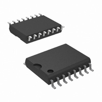
LM613IWM/NOPB National Semiconductor, LM613IWM/NOPB Datasheet - Page 19

LM613IWM/NOPB
Manufacturer Part Number
LM613IWM/NOPB
Description
IC COMP/REF/OPAMP DUAL 16SOIC
Manufacturer
National Semiconductor
Series
Super-Block™r
Type
Amplifier, Comparator, Referencer
Datasheet
1.LM613IWMNOPB.pdf
(25 pages)
Specifications of LM613IWM/NOPB
Applications
General Purpose
Mounting Type
Surface Mount
Package / Case
16-SOIC (0.300", 7.5mm Width)
Lead Free Status / RoHS Status
Lead free / RoHS Compliant
Other names
*LM613IWM
*LM613IWM/NOPB
LM613IWM
*LM613IWM/NOPB
LM613IWM
Available stocks
Company
Part Number
Manufacturer
Quantity
Price
Company:
Part Number:
LM613IWM/NOPB
Manufacturer:
Atmel
Quantity:
966
Application Information
Capacitors in parallel with the reference are allowed. See the
Reference AC Stability Range typical curve for capacitance
values — from 20 µA to 3 mA any capacitor value is stable.
With the reference’s wide stability range with resistive and
capacitive loads, a wide range of RC filter values will perform
noise filtering.
Adjustable Reference
The FEEDBACK pin allows the reference output voltage,
V
hold V
conduct current from Cathode to Anode; FEEDBACK current
always remains low. If FEEDBACK is connected to Anode,
then V
held at a constant voltage above Anode — say 3.76V for V
= 5V. Connecting a resistor across the constant V
a current I=R1/V
node. A Thevenin equivalent 3.76V is generated from FEED-
BACK to Anode with R2=3.76/I. Keep I greater than one
thousand times larger than FEEDBACK bias current for
temperature range (I≥5.5 µA for a 1% untrimmed error for a
commercial part).
<
ro
0.1% error — I≥32 µA for the military grade over the military
, to vary from 1.24V to 6.3V. The reference attempts to
FIGURE 4. Thevenin Equivalent of Reference
ro
r
at 1.24V. If V
= V
r
= 1.24V. For higher voltages FEEDBACK is
FIGURE 3. 1.2V Reference
r
flowing from Cathode into FEEDBACK
with 5V Output
r
is above 1.24V, the reference will
00922631
00922632
(Continued)
r
generates
ro
19
R1 = Vr/I = 1.24/32µ = 39k
R2 = R1 {(Vro/Vr) − 1} = 39k {(5/1.24) − 1)} = 118k
Understanding that V
resistors, and capacitors may be tied to the FEEDBACK pin,
a range of V
FIGURE 6. Output Voltage has Negative Temperature
FIGURE 5. Resistors R1 and R2 Program Reference
FIGURE 7. Output Voltage has Positive TC
Coefficient (TC) if R2 has Negative TC
r
temperature coefficients may be synthesized.
Output Voltage to be 5V
if R1 has Negative TC
r
is fixed and that voltage sources,
00922633
00922634
00922635
www.national.com


