AD532JD Analog Devices Inc, AD532JD Datasheet - Page 3
AD532JD
Manufacturer Part Number
AD532JD
Description
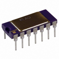
IC TRIMMED MULTIPLIER/DIV 14-DIP
Manufacturer
Analog Devices Inc
Specifications of AD532JD
Rohs Status
RoHS non-compliant
Function
Analog Multiplier/Divider
Number Of Bits/stages
4-Quadrant
Package / Case
14-CDIP (0.300", 7.62mm)
Supply Voltage Range
± 10V To ± 18V
Digital Ic Case Style
DIP
No. Of Pins
14
Operating Temperature Range
0°C To +70°C
Svhc
No SVHC (18-Jun-2010)
Operating Temperature Max
70°C
Operating
RoHS Compliant
Package Type
D-14 Side Brazed DIP
Temperature, Operating, Maximum
+70 °C
Temperature, Operating, Minimum
0 °C
Voltage, Supply
± 15 V (Typ.)
Lead Free Status / RoHS Status
Available stocks
Company
Part Number
Manufacturer
Quantity
Price

Part Number:
AD532JD
Manufacturer:
ADI/亚德诺
Quantity:
20 000


Model
AD532JD
AD532JD/+
AD532KD
AD532KD/+
AD532JH
AD532KH
AD532J Chip
AD532SD
AD532SD/883B
JM38510/13903BCA –55 C to +125 C
AD532SE/883B
AD532SH
AD532SH/883B
JM38510/13903BIA –55 C to +125 C
AD532S Chip
FUNCTIONAL DESCRIPTION
The functional block diagram for the AD532 is shown in Figure
1, and the complete schematic in Figure 2. In the multiplying
and squaring modes, Z is connected to the output to close the
feedback around the output op amp. (In the divide mode, it is
used as an input terminal.)
The X and Y inputs are fed to high impedance differential am-
plifiers featuring low distortion and good common-mode rejec-
tion. The amplifier voltage offsets are actively laser trimmed
to zero during production. The product of the two inputs is
resolved in the multiplier cell using Gilbert’s linearized trans-
conductance technique. The cell is laser trimmed to obtain
V
to obtain low output impedance and make possible self-contained
operation. The residual output voltage offset can be zeroed at
V
grounded.
REV. B
OUT
OS
in critical applications . . . otherwise the V
= (X
1
– X
2
)(Y
1
– Y
Temperature
Ranges
0 C to +70 C
0 C to +70 C
0 C to +70 C
0 C to +70 C
0 C to +70 C
0 C to +70 C
0 C to +70 C
–55 C to +125 C
–55 C to +125 C
–55 C to +125 C
–55 C to +125 C
–55 C to +125 C
–55 C to +125 C
2
)/10 volts. The built-in op amp is used
ORDERING GUIDE
Package
Descriptions
Side Brazed DIP
Side Brazed DIP
Side Brazed DIP
Side Brazed DIP
Header
Header
Chip
Side Brazed DIP
Side Brazed DIP
Side Brazed DIP
LCC
Header
Header
Header
Chip
OS
pin should be
Figure 2. Schematic Diagram
–3–
Package
Options
D-14
D-14
D-14
D-14
H-10A
H-10A
D-14
D-14
D-14
E-20A
H-10A
H-10A
H-10A
CHIP DIMENSIONS AND BONDING DIAGRAM
Figure 1. Functional Block Diagram
Dimensions shown in inches and (mm).
Contact factory for latest dimensions.
AD532
Related parts for AD532JD
Image
Part Number
Description
Manufacturer
Datasheet
Request
R

Part Number:
Description:
±1.7g Dual-Axis IMEMS Accelerometer Evaluation Board
Manufacturer:
Analog Devices Inc
Datasheet:

Part Number:
Description:
Inertial Sensor Evaluation System
Manufacturer:
Analog Devices Inc
Datasheet:
Part Number:
Description:
Manufacturer:
Analog Devices Inc
Datasheet:
Part Number:
Description:
Manufacturer:
Analog Devices Inc
Datasheet:
Part Number:
Description:
Manufacturer:
Analog Devices Inc
Datasheet:
Part Number:
Description:
Manufacturer:
Analog Devices Inc
Datasheet:
Part Number:
Description:
Manufacturer:
Analog Devices Inc
Datasheet:
Part Number:
Description:
Manufacturer:
Analog Devices Inc
Datasheet:
Part Number:
Description:
Manufacturer:
Analog Devices Inc
Datasheet:
Part Number:
Description:
Manufacturer:
Analog Devices Inc
Datasheet:
Part Number:
Description:
Manufacturer:
Analog Devices Inc
Datasheet:
Part Number:
Description:
Manufacturer:
Analog Devices Inc
Datasheet:
Part Number:
Description:
Manufacturer:
Analog Devices Inc
Datasheet: