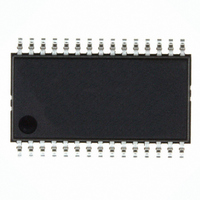
NJW1150M NJR, NJW1150M Datasheet

NJW1150M
Specifications of NJW1150M
Available stocks
Related parts for NJW1150M
NJW1150M Summary of contents
Page 1
... L, R-ch SDMP30 Tone Control Bass/Treble Balance Control Master Volume Level Trim 2 Power I C BUS Supply Interface 7.0V, +5V NJW1150 PACKAGE OUTLINE NJW1150M Lch TONE out Rch TONE out Lch out Rch out C-ch out SL-ch out SR-ch out SW-ch out - 1 - ...
Page 2
NJW1150 PIN FUNCTION 30 1 No. SYMBOL 1 GND Ground 2 V+ Positive power supply voltage 3 VDD Power supply voltage (Digital) 4 RTIN Tone control Right channel input 5 RTOUT Tone control Right channel output 6 RTC Tone control ...
Page 3
ABSOLUTE MAXIMUM RATING (Ta=25 C) PARAMETER Supply Voltage 1 Supply Voltage 2 Maximum Input Voltage Power Dissipation Operating Temperature Range Storage Temperature Range ELECTRICAL CHARACTERISTICS ( Ta=25 C,V PARAMETER Power Supply Operating Voltage 1 Operating Voltage 2 Supply Current 1 ...
Page 4
NJW1150 2 !TIMING ON THE I C BUS (SDA,SCL) SDA SCL t HD: LOW HD:DAT S !CHARACTERISTICS OF I/O STAGES FOR BUS Load Conditions STANDARD MODE: Pull up resistance ...
Page 5
OF BUS LINES (SDA,SCL) FOR I PARAMETER SCL clock frequency Hold time (repeated) START condition. Low period of the SCL clock High period of the SCL clock Set-up time for a repeated START condition NOTE) Data hold time Data ...
Page 6
NJW1150 TERMINAL DESCRIPTION PIN NO. SYMBOL 1 GND 2 V+ Positive power supply voltage 3 VDD Power supply voltag Tone control Right channel input 4 RTIN Left channel input 29 LTIN Tone control Right channel output 5 RTOUT Left channel ...
Page 7
TERMINAL DESCRIPTION PIN NO. SYMBOL Tone control 6 RTC Right channel Treble filter capacitor Left channel 27 LTC Treble filter capacitor Tone control Right channel 7 RBC1 Bass filter capacitor Left channel 26 LBC1 Bass filter capacitor Tone control Right ...
Page 8
NJW1150 TERMINAL DESCRIPTION PIN NO. SYMBOL Volume 10 LIN Left channel input 11 RIN Right channel input Center channel input 12 CIN 13 SLIN Surround Left channel input 14 SRIN Surround Right channel input 15 SWIN Sub Woofer channel input ...
Page 9
APPLICATION CIRCUIT GND 0V µ 100 F V+ +7V µ 100 F VDD +5V RTIN µ 4.7 F RTOUT RTC 10 nF RBC1 680nF RBC2 RBC3 µ LIN µ 4.7 F RIN µ 4.7 F CIN µ 4.7 ...
Page 10
NJW1150 Definition of cut-off frequency for Tone Control Cut-off frequency for Tone Control is adjustable with changing the capacitor C1 below circuit. See the next function for the cut-off frequency. Tone Control EX) C1 =10nF 680nF ...
Page 11
DEFINITION REGISTER BUS FORMAT S: Starting Term A: Acknowledge Bit MSB LSB S Slave Address 1bit 8bit SLAVE ADDRESS MSB R/W=0: Receive Only R/W=1: No Output Data CONTROL REGISTER TABLE ...
Page 12
NJW1150 CONTROL COMMAND TABLE Select Address 00H * 01H * 02H * 03H * 04H * 05H * 06H * - 12 - BIT ...
Page 13
CONTROL COMMAND TABLE Select Address TREBLE 07H 08H * BIT D3 D2 ...
Page 14
NJW1150 TYPICAL CHARACTERISTICS Operating Current vs. Supply Voltage Ta=25°C 10.0 9.0 8.0 7.0 6.0 5.0 4.0 3.0 2.0 1.0 0 Supply Voltage [V] Operating Current vs. Supply Voltage Ta=25°C 5.0 4.0 3.0 2.0 1.0 IDD ...
Page 15
TYPICAL CHARACTERISTICS Volume THD+N vs. Input Level Variation Ta=25° 0.1 0.01 0.001 -60 -40 -20 Input Level [dBV] Tone Control THD+N vs. Frequency Flat ( 0dB) Setting Ta=25° vi=0.1Vrms 0.1 1 vi=1Vrms 0.01 0.001 1 0.01 ...
Page 16
NJW1150 TYPICAL CHARACTERISTICS Volume Gain vs. Ambient Temperature V+=7V V-=-7V Vdd=5V, 0dB Setting 0.5 0.4 0.3 0.2 0.1 0.0 -0.1 -0.2 -0.3 -0.4 -0.5 -75 -50 - Ambient Temperature [°C] Volume Attenuation Level vs. Ambient Temperature V+=7V V-=-7V ...
Page 17
TYPICAL CHARACTERISTICS Volume THD+N vs. Ambient Temperature V+=7V V-=-7V Vdd=5V, 0dB Setting 10 1 THD_L,R,C,S L,SR,SW 0.1 0.01 0.001 -100 - Ambient Temperature [°C] Tone Control Output Level vs. Ambient Temperature V+=7V V-=-7V Vdd=5V BASS ...
Page 18
NJW1150 - 18 - [CAUTION] The specifications on this databook are only given for information , without any guarantee as regards either mistakes or omissions. The application circuits in this databook are described only to show representative usages of the ...


