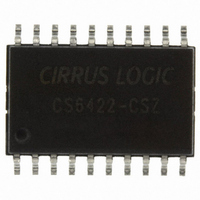
CS6422-CSZ Cirrus Logic Inc, CS6422-CSZ Datasheet - Page 4

CS6422-CSZ
Manufacturer Part Number
CS6422-CSZ
Description
IC SPEAKERPHONE ENHANCED 20SOIC
Manufacturer
Cirrus Logic Inc
Type
Audio Processorr
Datasheet
1.CS6422-CSZ.pdf
(48 pages)
Specifications of CS6422-CSZ
Package / Case
20-SOIC
Applications
Speakerphones
Mounting Type
Surface Mount
Product
General Purpose Audio Amplifiers
Available Set Gain
34 dB
Thd Plus Noise
0.03 %
Operating Supply Voltage
5 V
Supply Current
10 mA, 50 mA
Maximum Operating Temperature
+ 70 C
Mounting Style
SMD/SMT
Audio - Load Impedance
10 KOhms
Input Offset Voltage
2.12 V
Minimum Operating Temperature
0 C
Supply Voltage (max)
5.5 V
Supply Voltage (min)
4.5 V
Rohs Compliant
Yes
Operating Temperature Range
0°C To +70°C
Digital Ic Case Style
SOIC
No. Of Pins
20
Lead Free Status / RoHS Status
Lead free / RoHS Compliant
Lead Free Status / RoHS Status
Lead free / RoHS Compliant, Lead free / RoHS Compliant
Other names
598-1200-5
Available stocks
Company
Part Number
Manufacturer
Quantity
Price
Company:
Part Number:
CS6422-CSZ
Manufacturer:
CIRRUS
Quantity:
61
Company:
Part Number:
CS6422-CSZ
Manufacturer:
CIRRUS
Quantity:
4
Part Number:
CS6422-CSZ
Manufacturer:
CIRRUS
Quantity:
20 000
Company:
Part Number:
CS6422-CSZR
Manufacturer:
CREE
Quantity:
210
LIST OF FIGURES
LIST OF TABLES
4
4
5. PIN DESCRIPTIONS .............................................................................................................. 41
6. GLOSSARY ............................................................................................................................ 44
7. PACKAGE DIMENSIONS ....................................................................................................... 46
Figure 1. CLKI Timing ................................................................................................................... 7
Figure 2. Reset Timing .................................................................................................................. 7
Figure 3. Microcontroller Interface Timing ..................................................................................... 7
Figure 4. Typical Connection Diagram (Microphone Preamplifier Enabled) ................................. 8
Figure 5. Typical Connection Diagram (Microphone Preamplifier Disabled) ................................ 8
Figure 6. Analog Interface ........................................................................................................... 10
Figure 7. Microcontroller Interface .............................................................................................. 12
Figure 8. Suggested Layout ........................................................................................................ 29
Figure 9. Ground Planes ............................................................................................................. 30
Figure 10. Simplified Acoustic Echo Canceller Block Diagram ................................................... 31
Figure 11. How the AGC works (TVol = +30 dB) ........................................................................ 35
Table 1. Full scale voltages for each gain stage ........................................................................... 11
Table 2. MCR Control Register Mapping ...................................................................................... 12
Table 3. Register 0 Bit Definitions................................................................................................. 13
Table 4. Register 1 Bit Definitions................................................................................................. 16
Table 5. Register 2 Bit Definitions................................................................................................. 18
Table 6. Register 3 Bit Definitions................................................................................................. 21
Table 7. Register 4 Bit Definitions................................................................................................. 23
Table 8. Register 5 Bit Definitions................................................................................................. 25
4.2 Circuit Design ................................................................................................................... 37
4.3 System Design ................................................................................................................. 38
4.2.1 Interface Considerations ..................................................................................... 37
4.2.2 Grounding Considerations .................................................................................. 38
4.2.3 Layout Considerations ........................................................................................ 38
4.3.1 Gain Structure ..................................................................................................... 38
4.3.2 Testing Issues ..................................................................................................... 39
4.1.4.3 Double-talk Attenuation ....................................................................... 36
4.1.4.4 Noise Guard ........................................................................................ 37
4.2.1.1 Analog Interface .................................................................................. 37
4.2.1.2 Microcontroller Interface ...................................................................... 37
4.3.2.1 ERLE ................................................................................................... 39
4.3.2.2 Convergence Time .............................................................................. 40
4.3.2.3 Half-Duplex Switching ......................................................................... 40
CS6422
CS6422
DS295F1


