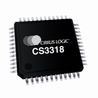
CS3318-CQZ Cirrus Logic Inc, CS3318-CQZ Datasheet - Page 4

CS3318-CQZ
Manufacturer Part Number
CS3318-CQZ
Description
IC ANLG VOL CTRL 8CH DGTL 48LQFP
Manufacturer
Cirrus Logic Inc
Type
Stereo Audio Volume Controlr
Datasheet
1.CS3318-CQZ.pdf
(44 pages)
Specifications of CS3318-CQZ
Package / Case
48-LQFP
Applications
High End Audio
Mounting Type
Surface Mount
Product
General Purpose Audio Amplifiers
Output Power
650 mW
Available Set Gain
22 dB
Thd Plus Noise
- 112 dB
Operating Supply Voltage
+/- 8 V to +/- 9 V, 3.3 V
Supply Current
36 mA
Maximum Operating Temperature
+ 70 C
Mounting Style
SMD/SMT
Audio Load Resistance
2 KOhms
Input Offset Voltage
0.75 V
Input Signal Type
Single
Minimum Operating Temperature
- 10 C
Output Signal Type
Analog
Supply Voltage (max)
9.45 V
Supply Voltage (min)
3.1 V
Output Type
8-Channel Audio
Lead Free Status / RoHS Status
Lead free / RoHS Compliant
For Use With
598-1497 - BOARD EVAL FOR CS3318 VOL CTRL
Lead Free Status / Rohs Status
Lead free / RoHS Compliant
Other names
598-1180
Available stocks
Company
Part Number
Manufacturer
Quantity
Price
Company:
Part Number:
CS3318-CQZ
Manufacturer:
CIRRUS
Quantity:
153
Company:
Part Number:
CS3318-CQZ
Manufacturer:
INTEL
Quantity:
38
Part Number:
CS3318-CQZ
Manufacturer:
CIRRUS
Quantity:
20 000
Company:
Part Number:
CS3318-CQZR
Manufacturer:
Cirrus Logic Inc
Quantity:
10 000
4
LIST OF FIGURES
LIST OF TABLES
Figure 1.Control Port Timing - I²C Format.................................................................................................. 10
Figure 2.Control Port Timing - SPI Format................................................................................................. 11
Figure 3.Typical Connection Diagram........................................................................................................ 12
Figure 4.Detailed Block Diagram ............................................................................................................... 13
Figure 5.CS3318 Control Mapping Matrix.................................................................................................. 17
Figure 6.Volume & Muting Control Implementation ................................................................................... 18
Figure 7.Standard I²C Connections............................................................................................................ 23
Figure 8.Standard SPI Connections........................................................................................................... 23
Figure 9.SPI Serial Control Connections ................................................................................................... 24
Figure 10.Individual Device Address Configuration Process ..................................................................... 25
Figure 11.I²C Serial Control Connections .................................................................................................. 26
Figure 12.Control Port Timing, I²C Write.................................................................................................... 27
Figure 13.Control Port Timing, I²C Read.................................................................................................... 28
Figure 14.SPI Write Cycle.......................................................................................................................... 28
Table 1. Example Volume Settings ............................................................................................................ 20
Table 2. Zero-Crossing Modes................................................................................................................... 22
Table 3. Zero-Crossing Time-Out Periods ................................................................................................. 22
Table 4. I²C Mode Default Chip Address ................................................................................................... 27
Table 5. Example Volume Settings ............................................................................................................ 31
Table 6. Example Volume Settings ............................................................................................................ 32
Table 7. Channel B = Channel A Settings ................................................................................................. 34
Table 8. Zero-Crossing Time-Out Settings ................................................................................................ 34
Table 9. Zero-Crossing Mode Settings ...................................................................................................... 35
Table 10. Chip Revision Register Codes ................................................................................................... 41
CS3318
DS693F1


